In the realm of industrial automation and electrical control systems, proximity sensors are indispensable components for non-contact detection. A dedicated test bench is crucial for validating sensor performance, calibrating parameters, and troubleshooting before field deployment. This guide details the systematic installation of a professional-grade proximity sensor test bench, adhering to industry best practices.
Phase 1: Pre-Installation Planning and Component Verification
Before any physical assembly, thorough planning is essential. Begin by reviewing the test bench design specifications, which should account for the types of sensors to be tested (inductive, capacitive, ultrasonic, photoelectric). Ensure the workbench or mounting platform is stable, level, and constructed from non-ferrous materials if testing inductive sensors to avoid interference. Verify all components have been received:
Test Bench Frame: A rigid, grounded metal structure.
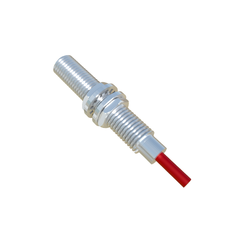
Motion System: Typically includes a linear slide or rotary stage with a precision actuator (stepper or servo motor) and controller. This simulates target movement.
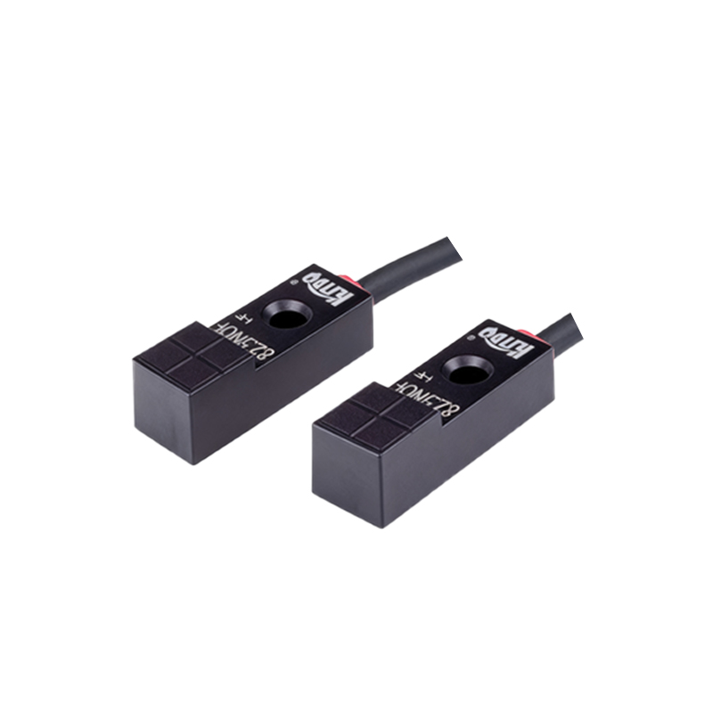
Target Fixture: A mount for various target materials (steel, aluminum, plastic, etc.) attached to the motion system.
Sensor Mounting Assembly: Adjustable brackets or clamps to securely hold sensors of different sizes and form factors (cylindrical, rectangular, etc.).
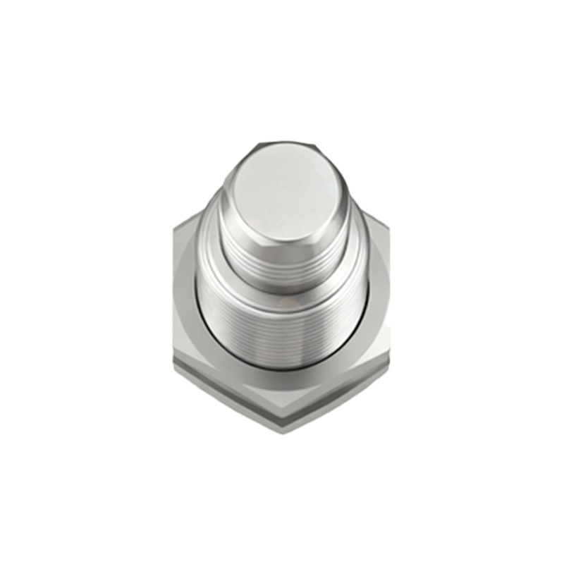
Signal Conditioning & Measurement Unit: This includes power supplies (12-24V DC standard), programmable logic controllers (PLCs) or data acquisition (DAQ) cards, relay modules, and measurement instruments like oscilloscopes or multimeters.
Wiring Harnesses: Pre-made cables with appropriate connectors (M8, M12) and proper gauge.
Safety Components: Emergency stop button, protective guarding, and warning labels.
Phase 2: Mechanical Assembly and Mounting
1. Assemble the Frame: Erect the main frame according to manufacturer instructions, ensuring all bolts are torqued to specification. Confirm the structure is free from wobble.
2. Install the Motion System: Mount the linear guide or rotary stage onto the frame bed. Align it precisely parallel to the intended axis of sensor testing. Attach the motor and actuator, connecting it mechanically to the slide or stage. Secure the target fixture to the moving part of the actuator.
3. Install Sensor Mounting Assemblies: Position the adjustable sensor holders opposite the target path. They should allow for precise micro-adjustments in all three axes (X, Y, Z) to vary the sensing distance. Ensure locking mechanisms are robust to prevent drift during vibration.
Phase 3: Electrical Wiring and Connection
This phase requires strict adherence to electrical safety standards (e.g., IEC 60204-1). De-energize all power sources during wiring.
1. Power Distribution: Mount and wire the main disconnect switch and power supply unit(s). Use separate supplies for the motion system (often higher current) and the sensor circuits. Implement proper fusing or circuit breakers for each branch.
2. Sensor Circuit Wiring: Run wiring from the sensor mounting area to the measurement unit. For 3-wire DC sensors, consistently connect the brown wire (+V), blue wire (0V/GND), and black wire (signal output). Use shielded cables for analog or high-frequency sensors, grounding the shield at one end only (typically the controller end) to prevent ground loops.
3. Controller Integration: Connect the sensor outputs to the PLC/DAQ input channels. Connect the motion controller to the actuator motor. Wire the emergency stop circuit in series with the main control power, ensuring it meets safety category requirements.
4. Grounding: Establish a single-point star ground or a robust ground bus bar. Connect the frame, all instrument chassis, cable shields, and power supply grounds to this point to minimize electromagnetic interference (EMI).
Phase 4: System Integration and Preliminary Check
1. Controller Programming: Upload the test sequence program to the PLC or motion controller. This program should command the actuator to move the target at defined speeds and positions while recording sensor response.
2. Measurement Setup: Configure the DAQ software or measurement instruments to capture key parameters: switching frequency, response time, hysteresis, and output signal stability.
3. Pre-Operational Check: Visually inspect all connections. Check for loose wires, pinched cables, or incorrect terminations. Manually move the actuator through its range to ensure smooth operation without obstruction.
Phase 5: Power-Up, Calibration, and Validation
1. Sequential Power-Up: First, apply power to the control system and measurement instruments. Then, energize the sensor power circuit. Finally, enable power to the motion system drive.
2. Basic Functionality Test: Manually trigger the emergency