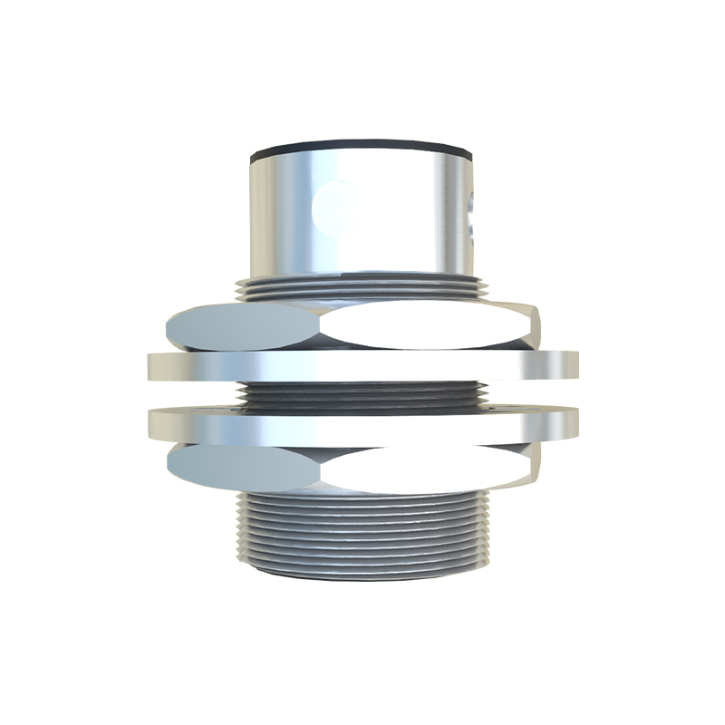
In the realm of industrial automation, the strategic placement of proximity sensors is paramount for ensuring system reliability, efficiency, and safety. A well-conceived layout design blueprint is not merely a diagram; it is the foundational plan that dictates the operational harmony between machinery and its control systems. This article delves into the critical considerations and best practices for creating an effective proximity sensor layout design, tailored for engineers and system integrators.
The primary objective of any sensor layout is to achieve optimal detection performance while mitigating interference and environmental challenges. Proximity sensors, including inductive, capacitive, and photoelectric types, each possess unique operational characteristics that must inform their placement. The first step in blueprint development involves a thorough analysis of the target object—its material composition, size, shape, and expected movement path. For instance, inductive sensors are ideal for metallic objects but require precise positioning relative to the target's approach axis. The sensing distance, often specified as the nominal range (Sn), must be carefully considered with a safety margin, typically 10-20% less than Sn, to account for mechanical tolerances and temperature variations.
Environmental factors exert a significant influence on layout design. In areas with high electromagnetic interference (EMI) from motors or variable frequency drives (VFDs), maintaining adequate separation between sensor cables and power lines is crucial. A minimum distance of 20-30 cm is generally recommended, with crossing at right angles if unavoidable. For harsh environments involving dust, coolant, or metal chips, the selection of sensors with appropriate ingress protection (IP) ratings, such as IP67 or IP69K, is non-negotiable. The layout must also facilitate easy access for maintenance and replacement without necessitating a full system shutdown. This often means positioning sensors on modular brackets or accessible machine faces rather than buried within deep enclosures.
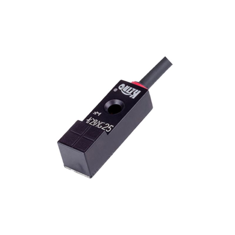
The electrical and network integration forms the backbone of the layout blueprint. Decisions regarding wiring topology—daisy-chaining versus home-run connections—impact both installation cost and diagnostic capability. For multi-sensor arrays, using a modular I/O system with standardized connectors can streamline wiring and reduce points of failure. The blueprint must clearly denote cable routing paths, junction box locations, and grounding points. Proper grounding is essential to shield against noise; a star-point grounding scheme for the sensor network is often superior to a daisy-chained ground. Furthermore, for designs incorporating IO-Link or other smart sensor protocols, the layout should account for the necessary master module placement and trunk line specifications to ensure stable digital communication.
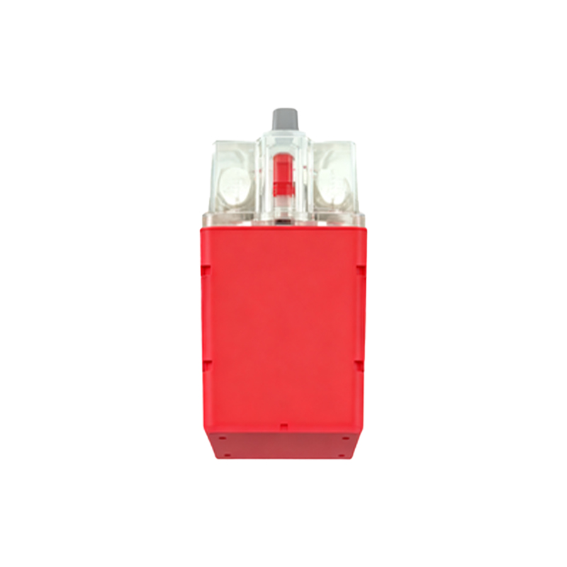
Mechanical integration is another layer of complexity. The mounting hardware—brackets, holders, and adjustable arms—must provide rigid support to prevent vibration-induced misalignment. The blueprint should specify torque values for mounting screws to avoid over-tightening, which can damage sensor housings. Consideration for potential physical obstructions, such as moving machine parts, tooling, or product flow, is vital. Using 3D CAD models in the blueprint phase to simulate the entire machine cycle can reveal interferences that 2D drawings might miss. For sensing small or fast-moving objects, the layout may require multiple sensors in a staggered or opposed configuration to guarantee detection reliability.
Finally, a robust layout design incorporates provisions for diagnostics and scalability. The strategic placement of diagnostic LEDs in visible locations, or the integration of sensor feedback into the Human-Machine Interface (HMI), aids in rapid troubleshooting. The blueprint should also allow for future modifications, such as adding sensors for new product variants, without requiring a complete redesign. This foresight involves leaving spare conduit space, unused I/O channels, and physical mounting points on machine frames.
In conclusion, a proximity sensor layout design blueprint is a multidisciplinary document that balances electrical, mechanical, and environmental constraints. It transcends simple placement to embody a system-level strategy for resilient automation. By adhering to these principles of target analysis, environmental hardening, integrated wiring, mechanical robustness, and forward-thinking diagnostics, engineers can craft layouts that maximize uptime and pave the way for the smart factories of tomorrow.