Laser sensors represent a critical technology in modern industrial automation, measurement systems, and safety applications. Their performance hinges significantly on the internal circuit architecture, which integrates optical, electronic, and signal processing components into a cohesive, high-precision system. This article delves into the core circuit design principles, key functional blocks, and operational analysis of typical laser sensor systems.
At the heart of a laser sensor is the laser diode driver circuit. This circuit must provide a stable, low-noise current to the laser diode to ensure consistent optical output power. It typically employs a constant current source topology, often using a precision operational amplifier and a MOSFET or bipolar transistor in a feedback loop. Thermal compensation is crucial here, as the laser diode's forward voltage and output wavelength are temperature-sensitive. Many designs incorporate a thermistor network and a separate temperature control circuit, or a Thermoelectric Cooler (TEC) driver, to stabilize the diode's operating temperature, thereby maintaining measurement accuracy.
The emitted laser beam interacts with the target and is reflected back to a photodetector, usually a photodiode or an avalanche photodiode (APD) for longer ranges or lower light conditions. The transimpedance amplifier (TIA) is the first and perhaps most critical stage in the receiver chain. It converts the photodetector's minute current signal into a usable voltage. Designing a high-gain, low-noise, and wide-bandwidth TIA is paramount. Key challenges include managing the photodetector's capacitance, minimizing input-referred noise (which sets the system's sensitivity limit), and preventing oscillation. Component selection, such as low-noise op-amps and careful PCB layout with guarding techniques, is essential.
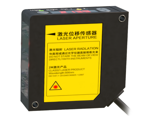
Following signal amplification, filtering circuits remove unwanted noise. This includes ambient light interference (often at power line frequencies like 50/60 Hz and their harmonics) and high-frequency electronic noise. A combination of band-pass or high-pass filters, sometimes synchronized with the laser modulation, extracts the signal of interest. For pulsed time-of-flight (ToF) sensors, the circuit must precisely measure the time delay between the emitted and received pulse. This involves high-speed comparators to detect pulse edges and a Time-to-Digital Converter (TDC) circuit with picosecond-level resolution. For phase-shift measurement ToF or triangulation sensors, a mixer or a phase-locked loop (PLL) circuit might be used to determine the phase difference between the transmitted and received modulated light.
The processed analog signal is then digitized by an Analog-to-Digital Converter (ADC). The resolution and speed of the ADC directly impact the sensor's precision and response time. A microcontroller unit (MCU) or a digital signal processor (DSP) forms the computational core. It executes algorithms for distance calculation, signal averaging, error correction (e.g., for ambient light or varying surface reflectivity), and communication protocol management. The firmware running on this processor is responsible for calibrating the sensor, linearizing the output, and implementing diagnostic functions.
Power management is another vital subsystem. Laser sensors often require multiple regulated voltage rails (e.g., +5V for digital logic, ±12V for analog stages, and a specific high voltage for APDs). Switch-mode power supplies (SMPS) are common for efficiency, but their switching noise must be meticulously filtered to prevent coupling into sensitive analog signal paths. Proper grounding and shielding strategies—separating analog, digital, and high-power grounds—are non-negotiable for stable operation in electrically noisy industrial environments.
Finally, the interface circuit enables communication with external systems, such as programmable logic controllers (PLCs). This can include standard digital outputs (PNP/NPN), analog outputs (0-10V, 4-20mA), or serial communication protocols like RS-485, IO-Link, or Ethernet/IP. Robust protection circuits against overvoltage, reverse polarity, and electromagnetic interference (EMI) are integrated here to ensure reliability.
In conclusion, the internal circuit of a laser sensor is a sophisticated synergy of analog and digital electronics, optoelectronics, and embedded software. Each subsystem, from the laser driver to the communication interface, must be meticulously designed and integrated to achieve the high levels of accuracy, speed, and robustness demanded by modern industrial applications. Continuous advancements in integrated circuits, such as specialized ToF sensor chips and low-power microcontrollers, are driving further miniaturization and performance enhancements in laser sensor technology.