In modern industrial automation, proximity switches play a critical role in detecting the presence or absence of objects without physical contact. With the advent of wireless sensor technology, integrating proximity switches into wireless networks has become increasingly common, offering flexibility, reduced wiring complexity, and enhanced scalability. This article provides a detailed guide to the wiring diagram for wireless sensor proximity switches, tailored for electrical engineers and technicians in the industry.
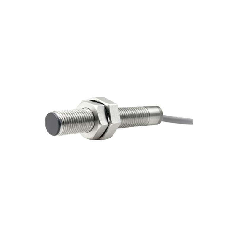
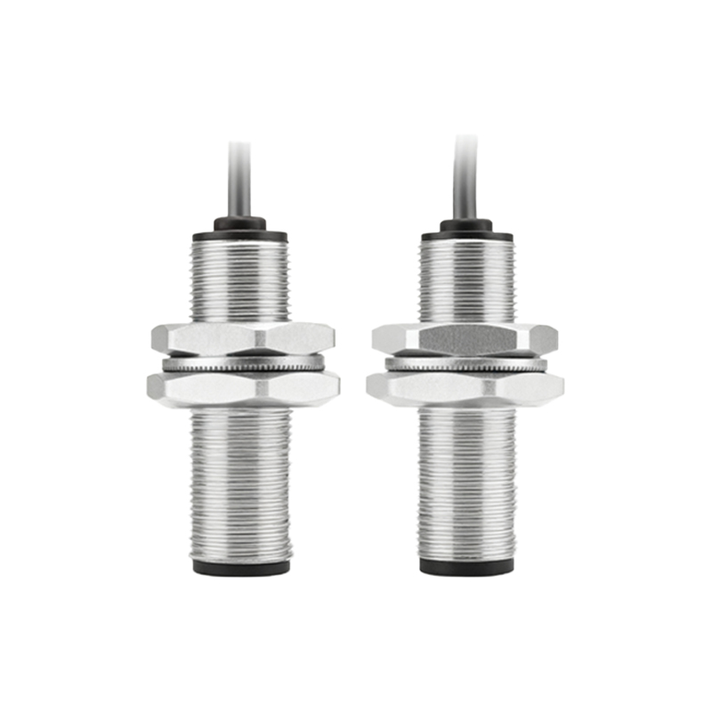
A typical wireless sensor proximity switch system consists of three main components: the proximity sensor itself, a wireless transmitter module, and a power supply unit. The proximity sensor, often based on inductive, capacitive, or photoelectric principles, detects objects within a specified range. When an object is detected, the sensor sends an electrical signal to the wireless transmitter. The transmitter then converts this signal into a wireless format, such as Wi-Fi, Bluetooth, or Zigbee, for communication with a central control system or receiver.
To create an effective wiring diagram, start by identifying the sensor's specifications. Most proximity switches have three or four wires: a power wire (usually labeled V+ or +24V DC), a ground wire (GND or 0V), an output wire (OUT or NO/NC for normally open/normally closed), and sometimes a separate wire for diagnostic functions. For wireless integration, the output wire must be connected to the input terminals of the wireless transmitter module. Ensure that the voltage levels match; for instance, if the sensor operates on 24V DC, the transmitter should support the same voltage range to prevent damage.

Next, connect the power supply to both the sensor and the transmitter. Use a regulated DC power source to provide stable voltage, as fluctuations can cause false triggers or communication errors. In the wiring diagram, illustrate clear connections: the positive terminal of the power supply links to the V+ wire of the sensor and the VCC pin of the transmitter, while the negative terminal connects to the GND wires of both devices. This parallel power configuration ensures both components receive adequate power without interference.
The output connection is crucial for signal transmission. Wire the sensor's output terminal to the digital input pin of the transmitter. If the sensor has a normally open (NO) configuration, it will close the circuit when an object is detected, sending a high signal to the transmitter. Conversely, a normally closed (NC) setup opens the circuit upon detection. Label these connections clearly in the diagram, using standard symbols such as lines for wires, circles for junctions, and icons for sensors and transmitters. For enhanced reliability, include a pull-up or pull-down resistor in the circuit if the transmitter requires it to stabilize the signal.
Antenna placement is another key aspect in wireless systems. In the wiring diagram, indicate the antenna connection point on the transmitter, typically via a coaxial cable or integrated antenna. Position the antenna away from metal surfaces or high-voltage equipment to minimize signal attenuation and electromagnetic interference. This ensures robust wireless communication over distances, which can range from 10 to 100 meters depending on the technology and environment.
Testing and troubleshooting should be part of the diagram notes. Include steps like verifying power with a multimeter, checking signal continuity, and monitoring wireless signal strength using dedicated tools. Emphasize safety precautions: always disconnect power before wiring, use insulated tools, and follow local electrical codes to prevent accidents.
In summary, a well-designed wiring diagram for wireless sensor proximity switches simplifies installation and maintenance. By accurately depicting connections between the sensor, transmitter, and power supply, engineers can achieve efficient object detection and seamless wireless data transmission. As industries move toward IoT and smart factories, mastering these diagrams is essential for optimizing automation systems and reducing downtime.