Hall effect proximity sensors are solid-state devices that detect the presence or absence of a magnetic field, and by extension, the presence of a ferromagnetic object or a permanent magnet. Unlike mechanical switches or optical sensors, they have no moving parts and are immune to dust, oil, and other environmental contaminants, making them exceptionally reliable for industrial and automotive applications. The core principle is the Hall effect: when a current-carrying conductor is placed in a magnetic field perpendicular to the current flow, a voltage difference, known as the Hall voltage, is generated across the conductor. This voltage is proportional to the strength of the magnetic field.
A basic Hall effect proximity sensor circuit consists of several key components. At its heart is the Hall effect sensor IC. Modern integrated circuits typically include not only the Hall element but also signal conditioning circuitry such as amplifiers, voltage regulators, Schmitt triggers, and an output stage. This integration simplifies design significantly. The sensor requires a stable DC power supply, usually between 3.5V and 24V depending on the model. A bypass capacitor placed close to the VCC and GND pins of the IC is crucial to filter out noise and ensure stable operation.
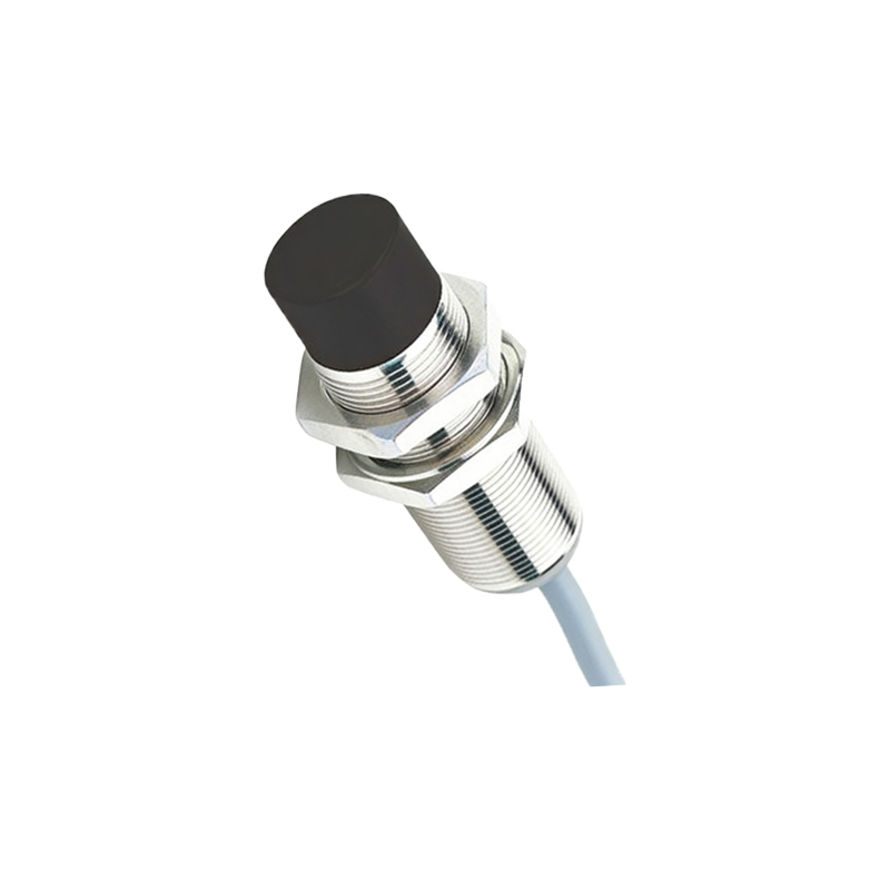
The output configuration is a critical design choice. There are two primary types: digital (switch) output and analog (linear) output. A digital Hall sensor, often called a Hall switch, provides a clean, on/off signal. When the magnetic flux density exceeds a predefined threshold (the operate point, B_OP), the output transistor switches state—either sinking current (open-collector NPN) or sourcing current. It remains in this state until the magnetic field decreases below a release point (B_RP), providing hysteresis to prevent chatter. This type is ideal for simple proximity detection, speed sensing (e.g., counting gear teeth), or position limits.
An analog Hall sensor outputs a voltage that is linearly proportional to the magnetic field strength passing through it. This output requires an analog-to-digital converter (ADC) on a microcontroller to interpret the precise field strength, enabling measurements of distance, current (in conjunction with a magnetic core), or subtle variations in field. For robust communication in noisy environments, some sensors feature a PWM (Pulse Width Modulation) output where the duty cycle corresponds to the magnetic field.
The magnetic source is equally important. For detecting ferrous metals (like iron or steel), a bias magnet is attached to the sensor assembly. The target object disturbs the magnetic field from this bias magnet, which is detected by the Hall IC. For detecting permanent magnets, the sensor responds directly to the magnet's field. The orientation of the magnetic field (North or South pole facing the sensor) matters and is specified in the datasheet. Shielding and the physical placement of the magnet relative to the sensor are vital for consistent sensing range and repeatability.
In practical circuit design, attention must be paid to the output interface. For a digital output connecting to a microcontroller, a pull-up resistor is typically required for an open-collector output. For driving heavier loads like relays or lamps, an external transistor or MOSFET may be necessary to handle the current. Transient voltage suppression diodes are recommended for automotive or inductive load applications to protect the sensor from voltage spikes and reverse polarity events.
The applications of Hall effect proximity sensor circuits are vast. In automotive systems, they are ubiquitous for sensing wheel speed for ABS, crankshaft/camshaft position, seatbelt buckle status, and gearbox position. In industrial automation, they provide non-contact end-of-travel detection on linear actuators, count products on conveyors, and confirm the closed position of safety doors. In consumer electronics, they detect the flip cover of a laptop or smartphone, enabling sleep/wake functions. Their durability, long operational life, and ability to work in harsh conditions make them a superior choice over mechanical limit switches in many demanding scenarios.
When designing with these sensors, consulting the manufacturer's datasheet is non-negotiable. Key parameters to review include the operating voltage range, output type and current capability, magnetic sensitivity thresholds (B_OP/B_RP), response time, temperature range, and package type. Proper design ensures reliable, maintenance-free operation for millions of cycles, solidifying the Hall effect sensor's role as a cornerstone of modern non-contact sensing technology.