Proximity switches, also known as proximity sensors, are widely used in industrial automation for non-contact detection of objects. Correct wiring is fundamental to their reliable operation and safety. This guide provides clear, step-by-step instructions for wiring common types of proximity switches, including both DC (NPN and PNP) and AC models.
Before starting any wiring work, the most critical step is to always disconnect power from the circuit. Verify the power is off using a appropriate voltage tester. Next, carefully examine the proximity switch's datasheet or nameplate. Identify its type (DC or AC), operating voltage range (e.g., 10-30V DC, 90-250V AC), output configuration (NPN normally open/closed, PNP normally open/closed), and the function of each wire. Typically, a 3-wire DC sensor will have brown (positive/+V), blue (negative/0V), and black (output signal) wires. A 2-wire AC sensor usually has two leads without polarity distinction.
For wiring a 3-wire DC proximity switch, follow this procedure. First, connect the power supply. For a PNP sensor (sourcing output), connect the brown wire to the positive DC supply terminal (+V). Connect the blue wire to the negative or common terminal (0V). The black output wire is then connected to the input terminal of your controller (like a PLC input module). The controller's input must be configured to receive a sourcing signal, meaning its common point is connected to 0V. For an NPN sensor (sinking output), the wiring is similar but the output logic is inverted. Connect brown to +V and blue to 0V as before. The black output wire now connects to the controller's input, but the controller's input common must be connected to +V to complete the circuit when the sensor activates. Incorrectly mixing PNP and NPN wiring with the controller will result in no signal.
Wiring a 2-wire AC proximity switch is simpler, as it acts like a switch in series with the load. One wire connects to the AC line voltage (e.g., L1), and the other wire connects to one terminal of the load (like a relay coil). The other terminal of the load then connects back to the neutral line (N). It is crucial to ensure the sensor's current rating is not exceeded by the load.
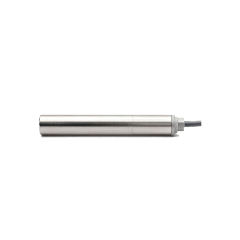
For 4-wire sensors, which contain two complementary outputs (e.g., one N.O. and one N.C.), the principle remains the same: identify the power wires and then connect the output wires to their respective destinations. Always use the correct gauge of wire for the current and secure connections with proper terminals, such as ferrule crimps, to prevent loose strands. After wiring, do not immediately restore full power. Perform a continuity check with a multimeter to ensure there are no dead shorts between wires. If possible, use a current-limited power supply for initial testing. Apply power and test the sensor's operation by bringing a target metal object (for inductive sensors) within its sensing range. Verify the output state changes correctly on your PLC or indicator light.
Common wiring mistakes include confusing NPN and PNP types, reversing polarity on DC sensors, overloading 2-wire sensors, and neglecting cable routing. Keep sensor cables away from high-power motor leads or AC power lines to prevent electrical noise interference, which can cause erratic operation. Use shielded cables in noisy environments and ground the shield properly at one end. Finally, secure all cables in cable ducts or with clamps to prevent strain on the electrical connections from vibration or accidental pulls. Proper wiring ensures not only functionality but also long-term stability and safety of the entire automated system.