Two-wire proximity sensors are widely used in industrial automation for detecting the presence or absence of objects without physical contact. These sensors operate on a simple yet effective principle, making them a popular choice for applications where space and wiring complexity are concerns. Unlike three-wire or four-wire sensors, two-wire models integrate seamlessly into control circuits with minimal wiring, reducing installation time and costs. This article delves into the working principle of two-wire proximity sensors, supported by explanatory diagrams to enhance understanding.
At the core of a two-wire proximity sensor is an oscillator circuit that generates a high-frequency electromagnetic field. When a metallic or conductive object enters this field, eddy currents are induced on the object's surface. These eddy currents absorb energy from the oscillator, causing a reduction in its amplitude. The sensor's detection circuit monitors this change and triggers a switching action. In two-wire sensors, this switching is typically achieved through a solid-state output, such as a transistor, which modulates the current flow in the circuit. The sensor operates in series with the load, meaning it draws a small leakage current even when in the "off" state to power its internal electronics.
A key aspect of two-wire proximity sensors is their wiring configuration. They are connected in series with the power supply and the load, similar to a traditional switch. The two wires serve dual purposes: they provide both power to the sensor and the switching path for the load. When no target is detected, the sensor allows a small standby current to flow, keeping the internal circuit active. Upon detection, the sensor increases the current flow to a level sufficient to drive the load, such as a relay or PLC input. This design eliminates the need for separate power and output wires, simplifying the overall system. However, it also imposes limitations on load compatibility and voltage drop considerations, which must be accounted for during selection.
To illustrate this, consider a typical wiring diagram. The diagram shows a DC power source connected in series with the sensor and the load. The sensor's internal components—oscillator, demodulator, and output stage—are depicted in a block layout. When a metal object approaches the sensing face, the oscillator's energy loss is detected, and the output stage switches to a low-resistance state, allowing current to energize the load. In contrast, when the object moves away, the output returns to a high-resistance state, reducing the current to the standby level. This on-off operation is fundamental to proximity sensing and is visually represented in timing diagrams that plot sensor response against target distance.
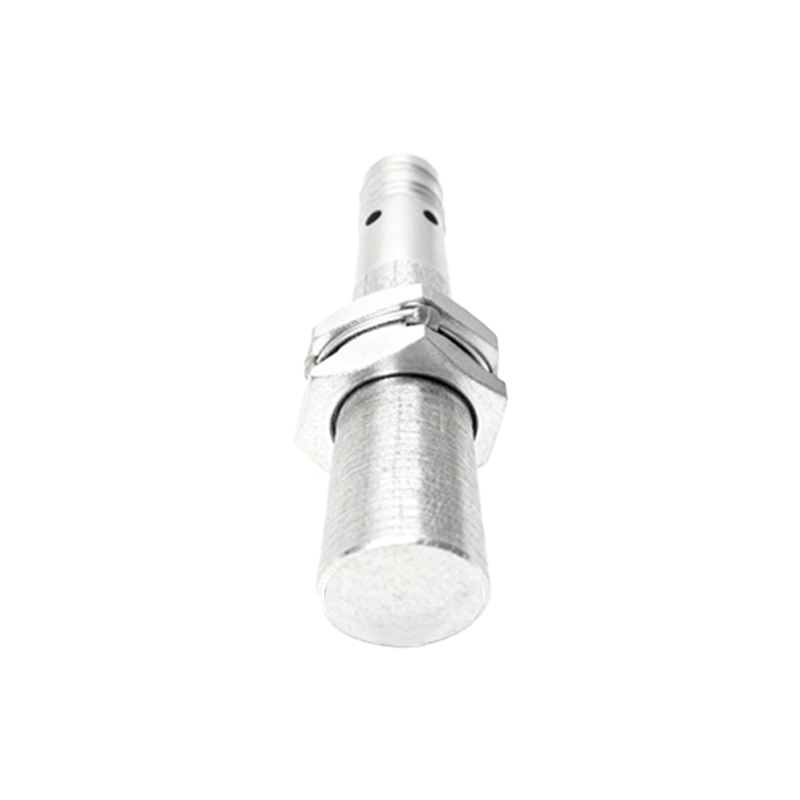
Two-wire proximity sensors are available in various types, including inductive, capacitive, and ultrasonic models, each suited to different materials and environments. Inductive sensors, the most common, detect metals only, while capacitive sensors can handle non-metallic objects. The choice depends on factors like sensing range, environmental conditions, and target composition. Diagrams often highlight these differences by showing field patterns and detection zones. For instance, an inductive sensor's electromagnetic field is depicted as concentric circles emanating from the sensing face, with the detection range marked clearly. Such visuals aid in proper installation and alignment to avoid false triggers.
In practice, two-wire sensors offer advantages like simplified wiring and cost-effectiveness, but they also have drawbacks, such as higher residual current and limited switching capacity. Engineers must evaluate these trade-offs based on application needs. Diagrams comparing two-wire with three-wire sensors can clarify these points, showing additional wiring for the latter and highlighting scenarios where each excels. For example, in high-speed or low-power applications, three-wire sensors might be preferable due to faster response times and lower leakage.
In conclusion, two-wire proximity sensors provide a reliable and efficient solution for object detection in automated systems. Their working principle, centered on electromagnetic induction and current modulation, is straightforward yet powerful when understood through diagrams. By integrating wiring schematics, block diagrams, and response graphs, this article aims to equip professionals with the knowledge to select, install, and troubleshoot these sensors effectively. As industry trends move towards smarter and more connected systems, mastering such fundamentals remains crucial for innovation and optimization in electrical engineering.