Proximity sensors are critical components in industrial automation, robotics, and safety systems, detecting the presence or absence of objects without physical contact. Common types include inductive, capacitive, ultrasonic, and photoelectric sensors. Determining whether a proximity sensor is functioning correctly involves systematic testing using visual inspections, electrical measurements, and performance checks. This guide provides step-by-step methods with diagrams to help engineers and technicians accurately assess sensor health.
First, perform a visual inspection. Examine the sensor body for cracks, corrosion, or damage, especially on the sensing face and housing. Check the cable and connector for wear, cuts, or loose connections. For wired sensors, ensure terminals are secure. Diagram 1 illustrates common physical defects: a cracked housing (A), corroded sensing face (B), and damaged cable insulation (C). Any visible issues may indicate failure or reduced lifespan.
Next, verify power supply and wiring. Most proximity sensors require a DC voltage (e.g., 12-24V DC) or AC supply, depending on the model. Refer to the sensor datasheet for specifications. Use a multimeter to measure voltage at the sensor terminals. Diagram 2 shows a typical wiring setup: power (V+) and ground (V-) connections, with the output wire (often black or blue) linked to a load like a PLC input. Ensure wiring matches the sensor type (e.g., NPN sinking or PNP sourcing). Incorrect wiring can cause malfunction or damage.
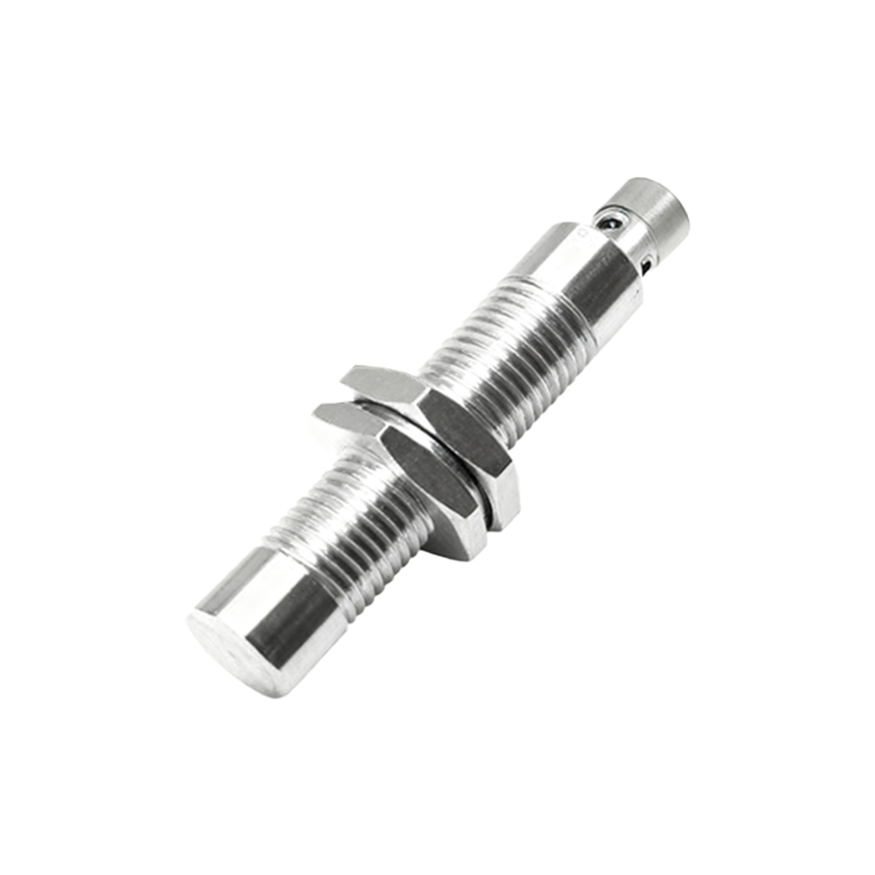
Test the sensor output. With power applied, bring a target object (e.g., a metal piece for inductive sensors) within the sensing range. Use a multimeter or oscilloscope to monitor the output signal. For digital sensors, the output should switch between high and low voltage states. Diagram 3 depicts output testing: when the target is absent, the output may be high (e.g., 24V); when present, it switches low (0V) for NPN types, or vice versa for PNP. Record the response time and consistency—delays or erratic switching suggest faults.
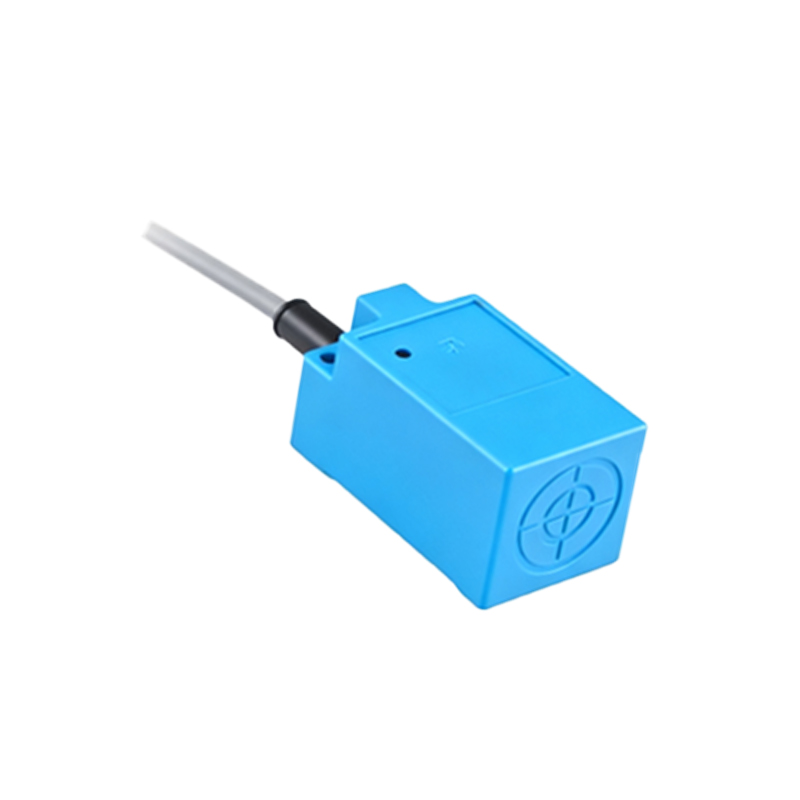
Measure sensing distance and repeatability. Place a target at the rated sensing distance (specified in the datasheet) and observe if the sensor activates. Gradually move the target closer and farther to check hysteresis. Diagram 4 demonstrates this test: a calibrated scale with target positions (D) and sensor activation points (E). Significant deviation from rated distance or inconsistent triggering indicates wear or calibration issues, common in aging sensors.
For advanced diagnostics, use an oscilloscope to analyze signal waveforms. Noise, spikes, or distorted pulses on the output line can reveal electrical problems like EMI interference or internal component failure. Diagram 5 shows ideal vs. faulty waveforms: a clean square wave (F) versus a noisy, irregular signal (G). Additionally, check current draw with a clamp meter; abnormal current (too high or low) may point to short circuits or internal damage.
Environmental factors also affect performance. Test sensors under actual operating conditions, considering temperature, humidity, and contaminants. For example, capacitive sensors can false-trigger with moisture, while ultrasonic sensors may struggle in noisy environments. Diagram 6 highlights environmental testing: a sensor in a simulated setting with heat (H), dust (I), and vibration (J). Compare results to baseline data—deviations warrant replacement or recalibration.
In summary, testing proximity sensors involves visual checks, electrical verification, output analysis, and environmental assessment. Regular maintenance using these methods can prevent downtime in industrial systems. Always consult manufacturer guidelines for specific procedures, as designs vary by type and brand.