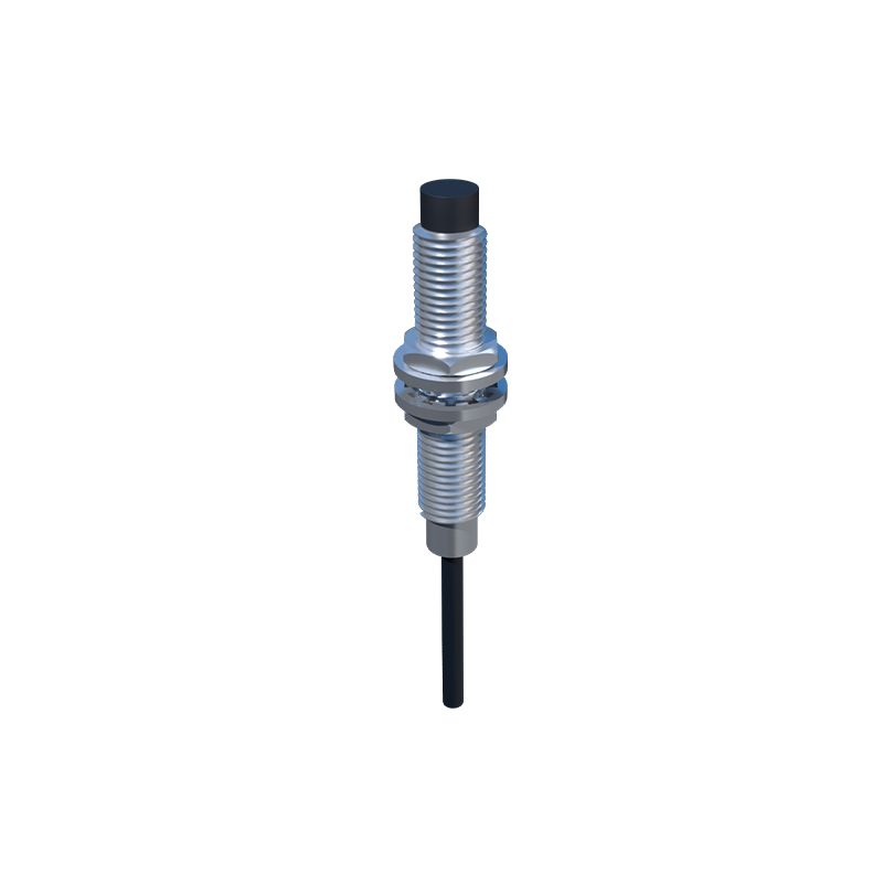
In industrial automation and machinery, proximity sensors are indispensable components for non-contact detection of objects. They ensure precise positioning, count items, and provide critical safety functions. However, a perplexing and potentially disruptive issue known as "proximity sensor reversal" can occur. This phenomenon does not refer to the physical sensor being installed backwards, but rather to a logical inversion of its output signal behavior. Understanding this issue is crucial for maintenance technicians and automation engineers to maintain system integrity and prevent costly downtime.
At its core, a standard proximity sensor, whether inductive, capacitive, or photoelectric, is designed to provide a specific output state when a target is within its sensing range. For instance, a normally open (NO) sensor closes its output circuit (becomes "on" or "high") when a target is detected. Conversely, a normally closed (NC) sensor opens its output circuit (becomes "off" or "low") upon detection. Sensor reversal flips this expected behavior. An NO sensor might remain off when a target is present and turn on when the target is absent, mimicking an NC sensor's logic, or vice-versa. This unexpected behavior can cause machinery to operate incorrectly, fail to start, or create hazardous conditions.
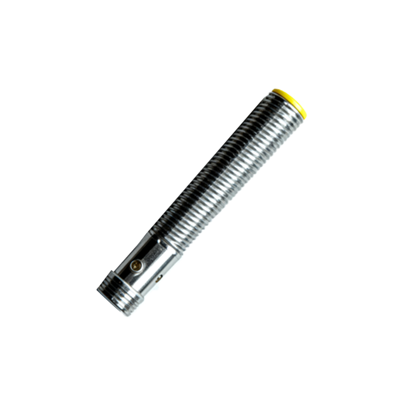
Several root causes can lead to this logical reversal. One of the most common is incorrect wiring or configuration. Many modern programmable sensors allow the user to select the operating mode (NO/NC) via a pushbutton, DIP switch, or software parameter. Accidentally changing this setting during maintenance or installation is a frequent culprit. Similarly, wiring the sensor's output to a sinking input when it's configured for sourcing, or vice-versa, in a DC circuit can cause an effective logical inversion. Another potential cause is internal sensor failure. Damaged output transistors or integrated circuits can become stuck in the opposite state or exhibit inverted switching characteristics. Environmental factors also play a role. Extreme electrical noise from nearby variable frequency drives (VFDs), welders, or high-current switches can induce voltage spikes that corrupt the sensor's signal, making it appear to toggle at the wrong times. For photoelectric sensors, issues like lens contamination, incorrect background suppression settings, or highly reflective targets can cause erratic behavior that mimics reversal.
Troubleshooting a suspected reversal requires a systematic approach. First, consult the sensor's datasheet and the machine's electrical diagrams to verify the intended operating mode (NO or NC) and wiring. Physically observe the sensor's indicator LED (if present) while introducing and removing a target. Does the LED illuminate upon detection? Compare this behavior to the documented specification. Next, use a digital multimeter to measure the output voltage or continuity directly at the sensor's terminals, independent of the connected controller (PLC, relay, etc.). This isolates the sensor from potential issues in the downstream wiring or input card. If the sensor's raw output behaves as specified, the problem may lie in the controller's input configuration. Check the PLC program to ensure the input address is correctly interpreted; sometimes a physical NO sensor is programmed in the logic as an NC contact, creating a functional reversal. For networked sensors, verify the configuration parameters in the control software.
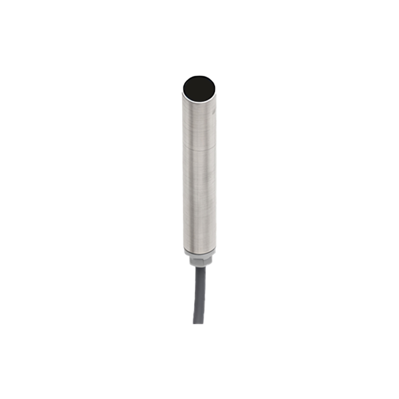
Preventing proximity sensor reversal is more efficient than troubleshooting it. Implement clear labeling during installation. Use permanent markers or labels to note the sensor type (e.g., "INDUCTIVE NO") on the device and in the cabinet. Maintain up-to-date documentation, including wiring diagrams and parameter lists. When replacing a sensor, always match the part number exactly and verify its default configuration before installation. For critical applications, consider using sensors with robust housing ratings (IP67 or higher) and built-in diagnostics to withstand harsh electrical and physical environments. Establishing a routine preventive maintenance schedule to check sensor operation and clean optical components can preempt failures that lead to erratic behavior.
In conclusion, proximity sensor reversal is a logical fault with physical consequences. It stems from configuration errors, wiring mistakes, hardware failure, or environmental interference. By understanding the operating principle of these sensors, methodically testing their output, and adhering to best practices in installation and documentation, engineers and technicians can swiftly resolve these issues and ensure the reliable, safe operation of automated systems. Recognizing that the sensor itself is rarely "backwards," but its signal is misinterpreted, is the first step toward an effective solution.