Wiring a proximity sensor might seem straightforward, but incorrect connections can lead to sensor failure, equipment damage, or even safety hazards. Whether you are an electrician, an automation engineer, or a DIY enthusiast, understanding the proper wiring methods is crucial for reliable operation. This guide provides a step-by-step approach to wiring common types of proximity sensors, focusing on practical techniques and essential precautions.
Proximity sensors are non-contact devices that detect the presence or absence of an object within a specific range. They are widely used in industrial automation, security systems, and consumer electronics. The most common types include inductive sensors (for detecting metals), capacitive sensors (for detecting both metals and non-metals), and photoelectric sensors. Each type has specific wiring requirements, but the fundamental principles are similar.
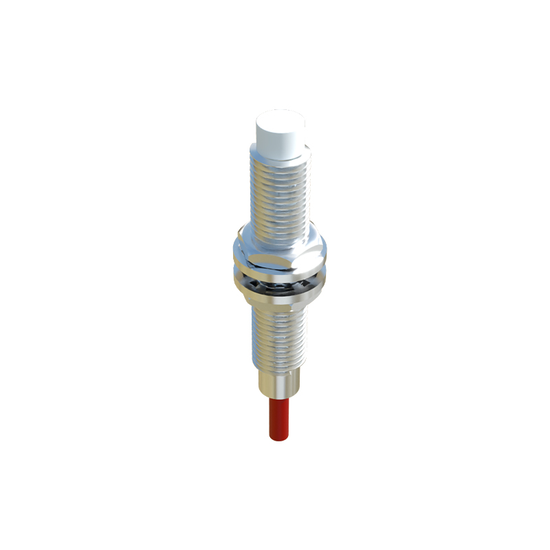
Before starting any wiring work, always ensure the power supply is disconnected. Verify the sensor’s specifications, including voltage rating (e.g., 10-30V DC or 90-250V AC), output type (NPN or PNP for DC sensors, NO or NC contacts), and housing material. The datasheet provided by the manufacturer is your primary reference—never overlook it.
For a typical three-wire DC proximity sensor, the wires are color-coded: brown for positive (+), blue for negative (-), and black for the output signal. In a standard NPN sensor configuration, connect the brown wire to the positive terminal of the power supply, the blue wire to the negative terminal, and the black wire to the load (such as a PLC input or relay). The load is then connected to the positive side to complete the circuit. For PNP sensors, the black output wire provides positive voltage when activated; thus, the load is connected to the negative side.
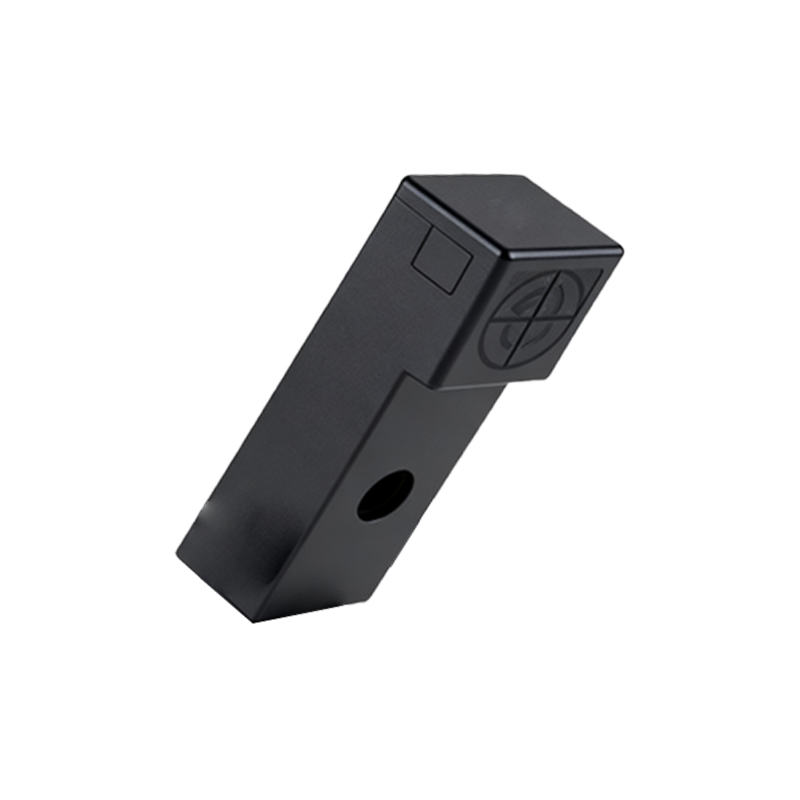
Two-wire AC sensors are simpler but require careful handling due to higher voltage. They typically have a brown (live) wire and a blue (neutral) wire. Connect the brown wire to the AC power source and the blue wire to the load. Since these sensors have a small leakage current even when off, using a compatible load is essential to avoid malfunction.
Shielded cables are recommended for long-distance wiring or environments with electromagnetic interference. Ground the shield at one end only, preferably near the controller, to prevent ground loops. Avoid running sensor cables parallel to high-voltage power lines; cross them at right angles if necessary.
After wiring, perform a thorough check. Inspect for loose connections, frayed wires, or incorrect polarity. Apply power and test the sensor with a target object. Use a multimeter to measure the output voltage or current, ensuring it matches the datasheet values. If the sensor fails to respond, recheck the wiring against the diagram and confirm the power supply stability.
Common mistakes include mixing up NPN and PNP wiring, ignoring load compatibility, and neglecting environmental factors like temperature or humidity. For instance, an inductive sensor placed too close to another metal object might trigger false signals. Maintain the recommended sensing distance and clean the sensor face regularly.
In summary, proper wiring ensures optimal performance and longevity of proximity sensors. Always prioritize safety by following electrical standards and manufacturer guidelines. With correct installation, these sensors can provide years of reliable service, enhancing efficiency in automated systems.