Proximity sensors are indispensable components in modern industrial automation, playing a critical role in object detection, position sensing, and machine control without physical contact. Understanding their wiring configurations is fundamental for proper installation, troubleshooting, and system integration. This comprehensive guide provides a complete visual and descriptive collection of wiring diagrams for various types of proximity sensors, serving as an essential resource for engineers, technicians, and maintenance personnel.
The core principle of a proximity sensor involves generating an electromagnetic field or beam. When a target object enters this field, it causes a change in the sensor's oscillation or signal, which is then converted into an electrical output signal. The wiring diagram is the roadmap that connects this sensing element to the broader control system, typically a Programmable Logic Controller (PLC). Incorrect wiring can lead to sensor failure, erratic machine behavior, or even damage to connected equipment.
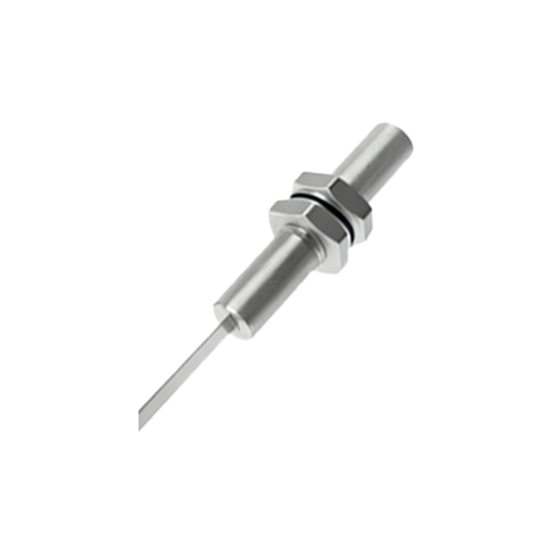
1. 2-Wire DC Proximity Sensor Wiring
The 2-wire sensor is the simplest type, functioning similarly to a switch. It has two terminals: one for DC positive (Brown wire typically) and one for DC negative/load (Blue wire typically). The load (e.g., a PLC input) is connected in series with the sensor. When the sensor detects an object, it closes the internal switch, allowing current to flow through the load to complete the circuit. The key consideration is the voltage drop across the sensor; the residual voltage at the load must be within the PLC's "ON" state threshold. These sensors are polarity-sensitive and must be connected correctly.
2. 3-Wire DC Proximity Sensor Wiring (NPN and PNP)
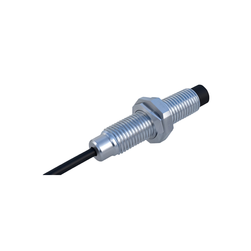
This is the most common configuration in industrial settings. It features three wires: Brown (V+), Blue (V- or 0V), and Black (Output Signal). The critical distinction is between NPN (Sinking) and PNP (Sourcing) outputs.
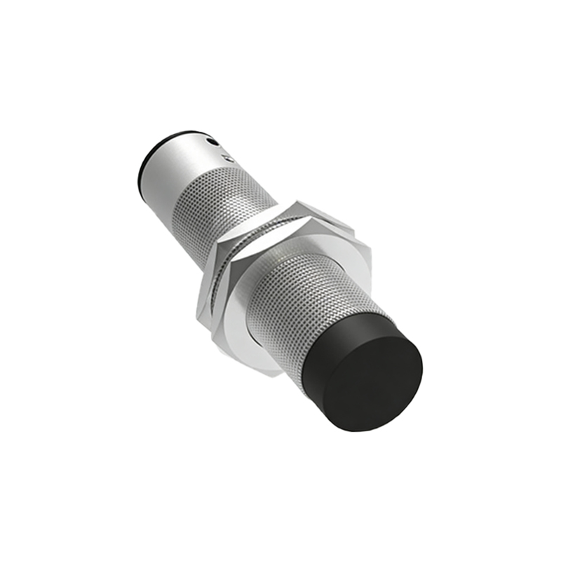
NPN Wiring Diagram: In an NPN sensor, the Black output wire acts as a switch to the Negative (0V) line. When active, it connects the load to 0V. The load (PLC input) is connected between the positive supply (Brown) and the sensor's Black output wire. This is a "sinking" output, meaning it sinks current into the sensor to complete the circuit to ground.
PNP Wiring Diagram: In a PNP sensor, the Black output wire acts as a switch to the Positive (V+) line. When active, it connects the load to V+. The load (PLC input) is connected between the sensor's Black output wire and the negative supply (Blue). This is a "sourcing" output, meaning it sources current from the sensor.
3. 3-Wire AC Proximity Sensor Wiring
These sensors operate directly on AC voltage (e.g., 120VAC, 240VAC). The standard wire colors are Brown (Live/L1), Blue (Neutral/L2), and Black (Output). The output is typically a solid-state switch (like a TRIAC) that closes between the Black and Blue wires upon detection. Proper grounding of the sensor body is crucial for safety and noise immunity. Always ensure the load's current rating does not exceed the sensor's switching capacity.
4. 4-Wire DC Proximity Sensor Wiring (Dual Output NPN/PNP)
Some advanced sensors provide both a Normally Open (NO) and a Normally Closed (NC) output from the same unit, often in a four-wire configuration: Brown (V+), Blue (V-), Black (NO output), and White (NC output). The wiring diagram shows how these two complementary signals can be used for redundancy, safety interlocking, or providing opposite logic states to different parts of a control system without needing an external inverter.
5. Analog Output Proximity Sensor Wiring
Analog sensors (e.g., 4-20mA, 0-10V) provide a continuous signal proportional to the distance to the target. Wiring involves the standard power supply connections (Brown/Blue) and one or two additional wires for the analog signal. For a 4-20mA output, the signal wire is typically connected to an analog input module on the PLC, which includes a precision resistor to convert the current loop into a measurable voltage. Shielding the analog signal wire is highly recommended to prevent electrical noise interference.
6. Namur Proximity Sensor Wiring
Used in intrinsically safe applications (like hazardous areas), Namur sensors are 2-wire devices that require an external interface amplifier or isolator. They output a small switching current (e.g.,<1mA for "OFF", >2mA for "ON") rather than directly driving a load. The wiring diagram illustrates the connection from the sensor to the specialized isolator