In modern industrial automation and precision measurement systems, laser sensors have become indispensable components due to their high accuracy, non-contact operation, and rapid response. The performance of these sensors, however, is heavily dependent on the design and implementation of their interface circuits. This article delves into the key considerations, design principles, and practical implementation strategies for laser sensor interface circuits, tailored for engineers and technical professionals in the electrical and industrial sectors.
The primary function of a laser sensor interface circuit is to condition the raw signal from the photodetector—typically a photodiode or a position-sensitive device (PSD)—into a clean, stable, and interpretable electrical signal for downstream processing by microcontrollers, programmable logic controllers (PLCs), or data acquisition systems. The design process begins with understanding the sensor's output characteristics. Common outputs include current from a photodiode in photovoltaic or photoconductive mode, or a voltage signal from an integrated sensor module. For current-output sensors, a transimpedance amplifier (TIA) is the cornerstone of the front-end circuit. The TIA converts the minute photocurrent, which can range from picoamperes to milliamperes depending on the laser intensity and distance, into a proportional voltage. Critical parameters in TIA design include the feedback resistor value, which sets the gain, and the feedback capacitor, which is essential for stability and bandwidth control to mitigate oscillations. Selecting an operational amplifier with low input bias current, low noise (both voltage and current noise), and adequate gain-bandwidth product is paramount. For instance, JFET-input or CMOS op-amps are often preferred for their exceptionally low input bias currents, which prevent significant error in measuring small photocurrents.
Following signal conversion, further conditioning is usually necessary. This stage often involves amplification, filtering, and offset adjustment. A second-stage amplifier can provide additional gain if the TIA output is insufficient. High-pass or low-pass filters are implemented to eliminate unwanted noise. In environments with significant ambient light interference—a common challenge—a modulated laser source paired with synchronous detection (often using a lock-in amplifier technique in the circuit) can dramatically improve the signal-to-noise ratio. The interface circuit must also account for the sensor's dynamic range. Automatic gain control (AGC) circuits or programmable gain amplifiers (PGAs) can be integrated to handle varying signal levels without saturation, ensuring consistent performance across different operating conditions.
For digital interface and communication, the analog signal must be digitized. An analog-to-digital converter (ADC) is selected based on required resolution (e.g., 12-bit, 16-bit) and sampling speed. To preserve signal integrity, proper grounding and shielding practices are non-negotiable. The sensor head and the interface circuit should be physically connected with shielded cables, and the circuit board layout must separate analog and digital grounds, using star grounding techniques to prevent ground loops. Power supply design is equally critical; low-noise, linear regulators are preferred over switching regulators for the analog sections to minimize ripple and switching noise that could couple into the sensitive signal path.
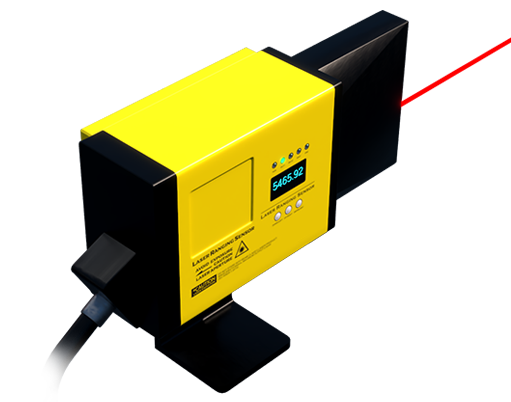
Implementation examples vary with application. In a laser triangulation displacement sensor, the interface circuit processes the position-dependent current from a PSD to calculate precise distance. In barcode scanners or LiDAR systems, the circuit must handle high-speed pulsed signals, requiring wide-bandwidth amplifiers and fast comparators for pulse detection. Robustness in industrial settings necessitates protection features against voltage transients, electrostatic discharge (ESD), and electromagnetic interference (EMI), often implemented with transient voltage suppression (TVS) diodes and ferrite beads.
In conclusion, designing an effective laser sensor interface circuit is a multidisciplinary task blending analog electronics, signal processing, and noise reduction techniques. A meticulous design approach—from front-end TIA selection to final digital conversion and protection—ensures that the high inherent precision of the laser sensor is fully realized in the final system output, enabling reliable operation in demanding industrial environments. Continuous testing and validation with the actual sensor under expected operating conditions are essential steps to refine the design and achieve optimal performance.