In industrial automation, interference-resistant proximity sensors are critical components for reliable object detection in electrically noisy environments. These sensors, often inductive or capacitive, are designed to minimize false triggers from electromagnetic interference (EMI), radio frequency interference (RFI), and other electrical noise. However, even robust sensors can malfunction. Effective troubleshooting and repair require a systematic approach, blending electrical knowledge with practical experience.
The first step in any repair process is accurate diagnosis. Begin by verifying the symptoms: Is the sensor failing to detect objects entirely, providing intermittent signals, or triggering falsely without a target present? Document the sensor model, its operating voltage (commonly 10-30V DC or 90-250V AC), and the output type (PNP, NPN, NO, NC). Use a multimeter to check the power supply at the sensor's terminals. Voltage drops or instability often point to power line issues, not the sensor itself. Next, inspect the physical condition. Look for visible damage to the housing, sensing face, or cable. Cracks, dents, or melted areas can indicate mechanical stress or thermal overload. Pay special attention to the cable entry point and connector, as strain relief failures are common.
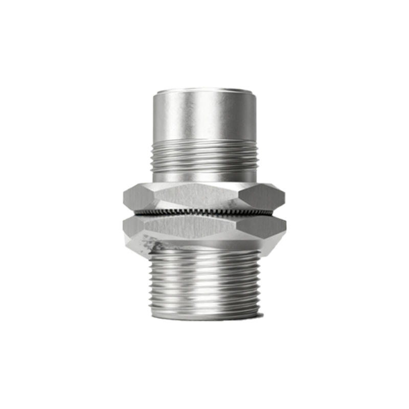
Electrical noise is a primary culprit for interference-resistant sensor failures. Despite their design, excessive noise can overwhelm internal filtering. To diagnose, monitor the sensor's output with an oscilloscope if possible. Look for signal noise or instability on the output line when the sensor is both active and idle. Grounding problems are a frequent source of interference. Ensure the sensor's housing is properly grounded and that the shield of the cable (if present) is connected correctly at the controller end, not both ends, to avoid ground loops. If noise is suspected, temporarily reroute the sensor's cable away from power lines, motor drives, or frequency inverters. A noticeable improvement suggests an EMI/RFI issue.
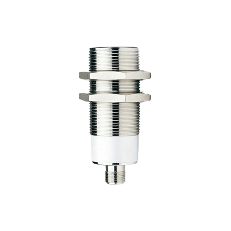
Internal component failure is another key area. Modern proximity sensors contain an oscillator coil, amplifier, comparator, and output switching circuit. A common failure point is the output transistor, which can short or open due to overcurrent, often from an incorrect load. Using the multimeter in diode-test mode, check the output transistor across the output and supply/ground pins (refer to the datasheet for pinout). A failed transistor typically requires board replacement or advanced soldering. The oscillator coil can degrade or break, especially in high-vibration settings. While direct coil testing is difficult without specialized equipment, a complete lack of response or a drastically reduced sensing range can indicate coil issues.
Environmental factors must not be overlooked. Contaminants like metal chips, oil, or coolant can coat the sensing face, attenuating the electromagnetic field. Clean the face thoroughly with a non-abrasive solvent. Ensure the target material and size are within specifications; some sensors are tuned for specific metals. Temperature extremes can also cause drift or failure. Verify the ambient temperature is within the sensor's rated range.
For repair, always consult the manufacturer's documentation. Some sensors are sealed and considered non-repairable; their repair may compromise IP ratings. For serviceable units, after disconnecting power, carefully open the housing. Inspect the printed circuit board (PCB) for burnt traces, bulging capacitors, or cracked solder joints. Reflowing solder on connectors and large components can fix intermittent problems. If a specific integrated circuit (IC) is identified as faulty, replacement is possible but requires surface-mount soldering skills.
After any repair, rigorous testing is essential. Reconnect the sensor in a controlled bench setup if possible. Use a known good target to verify the sensing distance, hysteresis, and output signal integrity. Finally, reinstall the sensor in its operational environment and monitor its performance under normal conditions.
Preventive maintenance reduces failure rates. Implement regular inspections, ensure proper cable management and grounding, and use noise suppression techniques like ferrite cores on cables near noise sources. Understanding the principles of interference-resistant design empowers engineers to not only fix sensors but also optimize the entire detection system for longevity and reliability.