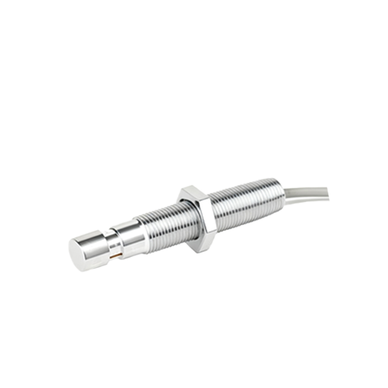
In the realm of industrial automation, vibratory feeders are indispensable for the precise orientation and transportation of components. At the heart of their reliable operation lies a critical sensing component: the proximity switch. This article delves into the technical specifics of proximity switches as applied to vibratory feeder sensing, examining their operational principles, selection criteria, and integration best practices from an electrical engineering perspective.
Proximity switches, often termed proximity sensors, are non-contact electronic devices designed to detect the presence or absence of a metallic target without physical interaction. In vibratory feeder applications, they are primarily employed for part presence detection, jam detection, and level control within the feeder bowl or on the track. The most prevalent technology for this duty is the inductive proximity sensor. Its operation is based on the principle of electromagnetic induction. The sensor's oscillator generates a high-frequency electromagnetic field emanating from its active face. When a metallic target—such as a screw, bracket, or the feeder bowl itself—enters this field, eddy currents are induced on the target's surface. This causes a load on the oscillator, leading to a change in the oscillation amplitude. This change is detected by the sensor's threshold circuit, which subsequently triggers a solid-state output switch (typically NPN or PNP, sinking or sourcing).
Key electrical specifications demand careful consideration. The sensing distance, or nominal range (Sn), is crucial. For feeder applications, a standard range of 2mm to 15mm is common, ensuring reliable detection without interference from vibration-induced positional variance. Engineers must account for the reduction factor, which decreases the effective sensing distance for metals other than mild steel (e.g., stainless steel, aluminum, copper). The operating frequency, or switching frequency, indicates how quickly the sensor can respond to targets passing by. For high-speed feeders, sensors with frequencies of 1kHz or higher are necessary to avoid missed counts. Output configuration is another vital parameter. DC 3-wire sensors are standard, with PNP (sourcing) and NPN (sinking) outputs. The choice must align with the controller's input card specifications (e.g., PLC). Protection class ratings are non-negotiable in industrial environments. A minimum of IP67 is recommended to withstand washdowns, dust, and coolant exposure common in machining or assembly lines where feeders are deployed.
Integration into the vibratory feeder control system involves more than just wiring. The sensor is typically mounted on a bracket adjacent to the feeder track or bowl. Precise alignment is essential to ensure consistent detection. The output signal is wired to the feeder's control unit or directly to a PLC. This signal can be used to halt the feeder in case of a jam (no part detected when expected) or to modulate feeder amplitude via a variable frequency drive to maintain optimal part flow. Electrical noise from the feeder's electromagnetic coil is a significant challenge. The intense AC field can cause false triggering or erratic sensor behavior. Mitigation strategies include using shielded cables, ensuring proper grounding of both the sensor and feeder body, maintaining physical separation between sensor wiring and power lines to the coil, and selecting sensors with robust noise immunity ratings. Some advanced models feature built-in surge protection and are specifically designed for high-noise environments.
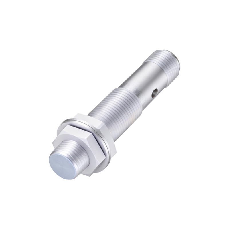
When selecting a proximity switch for a vibratory feeder, engineers should evaluate the target material, required sensing distance, environmental conditions (temperature, contaminants), electrical requirements (voltage, output type), and the mechanical demands of mounting. Tubular (cylindrical) M8, M12, or M18 threaded housings are prevalent for their ease of installation. Regular maintenance, though minimal, involves checking for physical damage, buildup of debris on the sensing face, and verifying the stability of the output signal.
In summary, the proper application of proximity switches is fundamental to achieving high reliability and efficiency in vibratory feeder systems. A thorough understanding of their electrical characteristics and environmental interactions allows engineers to design robust sensing solutions that minimize downtime and ensure seamless integration into automated production processes. The choice is not merely about detecting an object; it's about ensuring the continuity and precision of the entire material handling operation.