In industrial automation and control systems, proximity sensors are indispensable components for detecting the presence or absence of objects without physical contact. A critical aspect of their application involves connecting external loads, which directly impacts sensor performance, reliability, and system safety. This article delves into the concept of external loads for proximity sensors, exploring their types, selection criteria, and practical considerations for optimal integration.
An external load refers to the electrical device or circuit connected to the output of a proximity sensor. When the sensor detects a target within its sensing range, it switches its output state to control this load. Common examples include relays, solenoids, PLC (Programmable Logic Controller) input modules, indicator lights, and contactors. The load essentially acts as the "action" component, translating the sensor's signal into a tangible operation, such as activating a machine, triggering an alarm, or logging data.
Proximity sensors typically feature two primary output types: solid-state (transistor-based) and relay outputs. Solid-state outputs, including PNP (sourcing) and NPN (sinking) configurations, are designed for fast switching and long life but have limited current-carrying capacity. They often require careful matching with loads like PLC inputs or small relays. Relay outputs, on the other hand, can handle higher currents and voltages, making them suitable for direct control of heavier loads like motors or large contactors, though they may wear out over time due to mechanical contacts.
Selecting an appropriate external load hinges on several key parameters. First, consider the sensor's output specifications: maximum load current, voltage rating, and switching capacity. Exceeding these limits can cause overheating, failure, or safety hazards. For instance, a sensor rated for 200mA should not drive a load drawing 500mA without an intermediate amplifier or relay. Second, assess the load's electrical characteristics, such as inrush current (common in inductive loads like solenoids) and steady-state current. Inductive loads can generate voltage spikes during switching, potentially damaging solid-state outputs; thus, protective measures like flyback diodes or surge suppressors are often necessary.
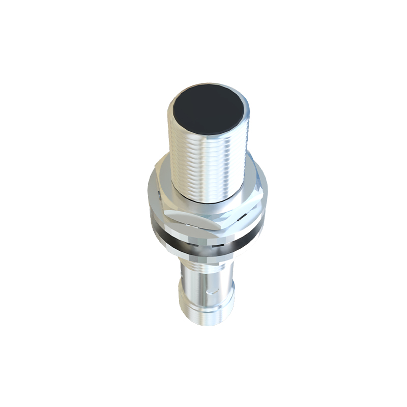
In practice, engineers must also account for environmental factors and wiring practices. Long cable runs between the sensor and load can introduce capacitance or interference, affecting signal integrity. Using shielded cables and proper grounding mitigates noise issues. Additionally, for DC sensors, ensuring correct polarity is crucial—mismatching PNP and NNP configurations with loads can lead to malfunction. In AC applications, attention to voltage compatibility and phase alignment is essential to avoid equipment damage.
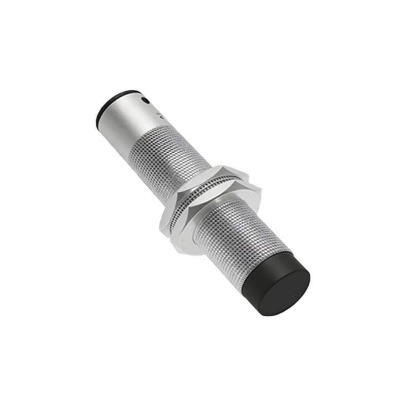
A real-world example illustrates these principles: In a conveyor system, a capacitive proximity sensor detects plastic containers and signals a pneumatic valve (solenoid) to divert them. The solenoid, an inductive load, has an inrush current of 300mA, while the sensor's solid-state output supports up to 250mA. To bridge this gap, a relay is interposed—the sensor switches the relay coil (low current), and the relay contacts handle the solenoid's higher current. This setup extends sensor life and ensures reliable operation.
Ultimately, understanding external loads is vital for designing robust automation systems. By aligning load requirements with sensor capabilities, engineers enhance efficiency, reduce downtime, and maintain safety standards. Always refer to manufacturer datasheets and industry guidelines, such as IEC 60947-5-2, for detailed specifications and best practices in proximity sensor applications.