In industrial automation and control systems, the precise management of motor direction is critical for numerous applications, from conveyor belts to robotic arms. One effective method to achieve this control is through the integration of proximity sensors, which provide non-contact detection of objects, enabling automated and reliable motor reversal. This article delves into the principles, circuit design, and implementation of using proximity sensors to control the forward and reverse operation of three-phase AC induction motors or DC motors, adhering to standard industry practices.
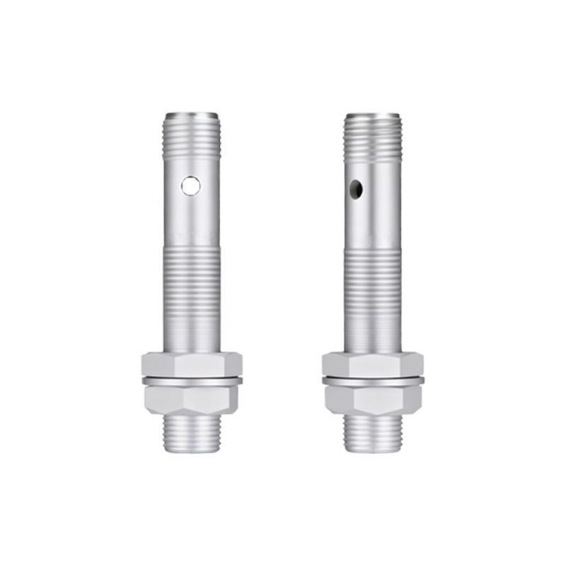
Proximity sensors, typically inductive or capacitive types, detect the presence of metallic or non-metallic objects without physical contact. When an object enters the sensor's detection range, it triggers an output signal—usually a digital switch (PNP or NNP) or an analog voltage. For motor control, this signal is processed by a control unit, such as a Programmable Logic Controller (PLC) or a relay-based circuit, to change the motor's rotational direction. The core idea involves using two proximity sensors: one positioned to detect an object at the forward limit, and another at the reverse limit. Upon detection, the sensor sends a signal to halt the current direction and initiate the opposite rotation, ensuring the motor operates within a defined range and prevents mechanical overtravel.
The circuit configuration for this setup commonly includes a motor driver or contactor system. For a three-phase motor, a forward-reverse starter circuit with two contactors is employed, interlocked to prevent simultaneous activation that could cause short circuits. The proximity sensors are wired into the control circuit, often in series with safety relays or directly into PLC input modules. When Sensor A (forward limit) detects an object, it de-energizes the forward contactor and energizes the reverse contactor after a brief delay, causing the motor to reverse. Conversely, Sensor B (reverse limit) triggers the switch back to forward motion. This creates an automated reciprocating cycle, ideal for applications like automated sliding doors or packaging machinery.
Implementation requires careful calibration of sensor placement and sensitivity. The sensors must be mounted at precise locations to accurately define the travel endpoints, and their detection range should be adjusted to avoid false triggers from environmental interference. In PLC-based systems, ladder logic programming is used to handle the sensor inputs and control outputs. A simple program might include routines to monitor sensor status, manage timers for direction change delays, and incorporate emergency stop functions. For DC motors, an H-bridge circuit can be used, with the proximity sensor signals fed into microcontroller inputs to switch the polarity of the motor supply, thereby reversing direction.
Safety and reliability are paramount in such systems. Redundant sensors or fail-safe mechanisms should be considered to handle sensor failures, and overload protection devices like circuit breakers must be integrated. Regular maintenance, including checking sensor alignment and cleaning sensing surfaces, ensures long-term operation. Additionally, compliance with industry standards such as IEC 60947 for control circuits and ISO 13849 for safety-related parts is recommended.
In summary, using proximity sensors for motor forward-reverse control enhances automation efficiency, reduces manual intervention, and minimizes wear on mechanical components. By leveraging non-contact sensing technology, industries can achieve precise, repeatable motion control in diverse applications, from manufacturing lines to material handling systems. This approach not only optimizes performance but also contributes to safer and more energy-efficient operations.