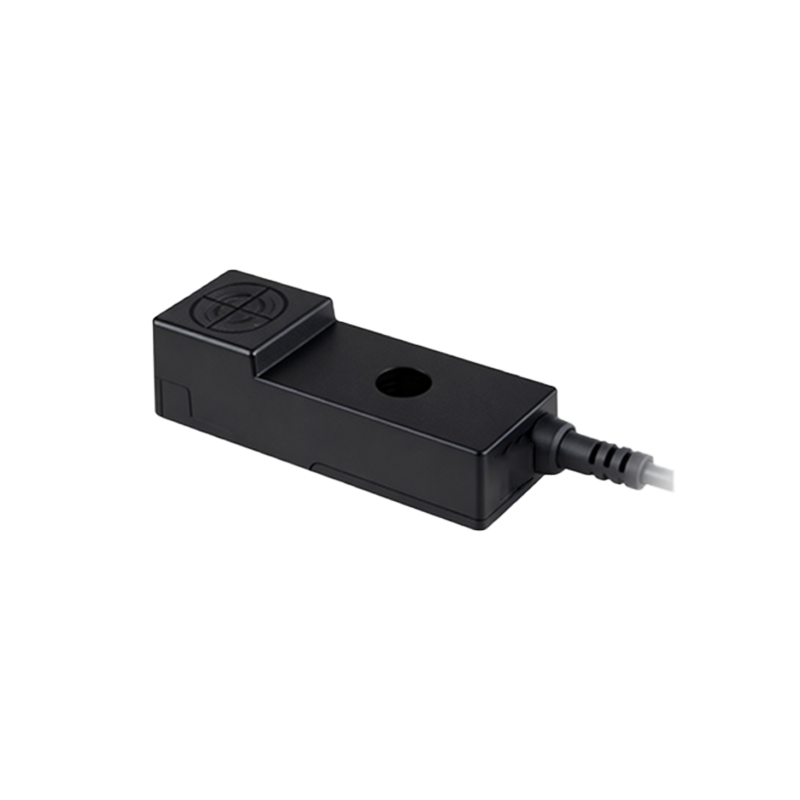
In industrial automation and control systems, proximity sensors play a critical role in detecting the presence or absence of objects without physical contact. Among various types, 5-wire proximity sensors are widely utilized due to their enhanced functionality and reliability. This article provides a comprehensive guide to the wiring configuration of 5-wire proximity sensors, covering principles, step-by-step procedures, and best practices for optimal performance.
A 5-wire proximity sensor typically consists of two power supply wires, two output wires, and one wire for diagnostic or auxiliary functions. The power supply wires are usually designated as brown (positive) and blue (negative), connecting to a DC power source, commonly 10-30 VDC. The output wires, often black and white, correspond to the sensor's switching signals—normally open (NO) or normally closed (NC) configurations. The fifth wire, typically gray, may serve as a diagnostic output, providing status indicators such as short-circuit protection or operational alerts.
Before initiating the wiring process, it is essential to verify the sensor's specifications, including voltage ratings, output type (PNP or NPN), and load capacity. Incorrect wiring can lead to sensor damage or system malfunctions. Begin by disconnecting the power source to ensure safety. Connect the brown wire to the positive terminal of the power supply and the blue wire to the negative terminal. For the output, if using a PNP sensor, the black wire (NO) or white wire (NC) should be connected to the load, which is then linked to the power supply's negative side. In NPN configurations, the output wire connects to the load, which is tied to the positive supply. The gray wire, if applicable, should be connected according to the manufacturer's instructions—often to a monitoring device or controller for diagnostic feedback.
Proper grounding and shielding are crucial to minimize electrical noise and interference, especially in environments with high-frequency equipment. Use twisted-pair cables for the power and output lines, and ensure all connections are secure and insulated. After wiring, perform a functional test by applying power and introducing a target object within the sensor's sensing range. Verify that the output switches correctly and that any diagnostic functions operate as intended.
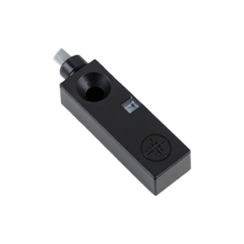
Regular maintenance, including checking for loose connections and environmental factors like dust or moisture, can prolong sensor life. By adhering to these wiring guidelines, engineers can ensure reliable operation and integrate 5-wire proximity sensors seamlessly into complex industrial systems, enhancing efficiency and safety.