Proper grounding of laser sensors is a critical aspect of ensuring reliable operation, measurement accuracy, and long-term system stability in industrial environments. Laser sensors, used for precise distance measurement, positioning, and object detection, are sensitive electronic devices. Inadequate grounding can lead to erratic readings, signal noise, intermittent failures, or even permanent damage from electrical transients. This guide outlines the fundamental principles and best practices for grounding laser sensors effectively.
The primary purpose of grounding is to provide a safe, low-impedance path for fault currents and unwanted electrical noise to dissipate, thereby protecting both equipment and personnel. For laser sensors, grounding serves two key functions: safety grounding (or protective earth) and signal reference grounding (or technical ground). Safety grounding is mandatory and connects the sensor's metal chassis or enclosure to the earth ground to prevent electric shock. Signal reference grounding aims to create a stable reference voltage (common zero-potential point) for the sensor's internal circuitry and its communication signals, minimizing electromagnetic interference (EMI).
Before installation, consult the sensor's manufacturer documentation. Specifications will detail grounding requirements, including terminal designations (often labeled "GND," "PE," or with the earth symbol). Identify if the sensor has separate terminals for chassis ground and signal ground. Some high-precision models require isolated or floating grounds to prevent ground loops.
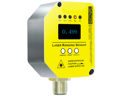
A robust grounding system starts with the main facility ground point, typically a grounding rod or bus bar. Use a dedicated, thick-gauge copper wire (e.g., 12 AWG or larger, as per local electrical codes) to connect the sensor's protective earth terminal directly to this point. The connection must be tight and corrosion-free; use star washers or crimp lugs to ensure metal-to-metal contact. Avoid daisy-chaining grounds from multiple devices on a single wire, as this increases impedance and can cause ground loops. Instead, use a star topology where each device has its own ground wire running to a common ground point.
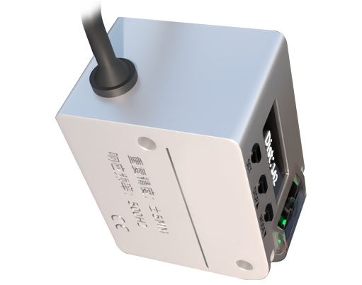
For the signal reference, the strategy depends on the sensor's output type and system architecture. For analog output sensors (e.g., 4-20mA, 0-10V), it is often recommended to connect the signal ground wire (the negative or return line) to the same stable ground point as the power supply's common terminal at the controller or PLC input card. This establishes a single-point ground for the signal circuit. Shielded cables are essential for analog and digital communication lines (like RS-485 or IO-Link). The cable shield must be grounded at one end only, typically at the controller or system ground side, to drain noise without creating a ground loop. Use clamp-on ferrite cores near the sensor connector if high-frequency noise is suspected.
In systems involving multiple sensors and controllers, ground potential differences between distant locations can induce currents in ground wires, known as ground loops. These can introduce significant noise into measurement signals. To mitigate this, ensure all equipment is bonded to a single, high-quality ground grid. For sensors in extremely noisy environments or when connected to sensitive data acquisition systems, consider using signal isolators or converters that provide galvanic isolation between the sensor and the receiving device.

Regular maintenance is crucial. Periodically inspect ground connections for looseness, corrosion, or physical damage. Measure the resistance between the sensor chassis and the main ground point; it should typically be below 1 ohm. Use an earth ground tester for accurate readings.
In summary, effective grounding of laser sensors is not an afterthought but a foundational design requirement. By implementing a dedicated safety ground, managing signal references carefully, using proper cabling and shielding, and avoiding ground loops, engineers can maximize sensor performance, reduce downtime, and ensure a safe working environment. Always prioritize the specific instructions provided by the sensor manufacturer and adhere to all applicable national and international electrical standards, such as IEC 60204-1 and NFPA 79.