In industrial automation and motion control systems, sensors are the critical components that translate physical phenomena into actionable electrical signals. Two common devices often encountered in machinery—particularly in speed monitoring and position detection—are gear speed sensors and proximity switches. While they may sometimes be used in similar mechanical environments, their operating principles, primary functions, and typical applications are fundamentally different. Understanding these distinctions is essential for proper sensor selection, system design, and troubleshooting.
A gear speed sensor, often referred to as a gear tooth sensor or variable reluctance sensor, is specifically designed to detect the rotational speed of a gear or a toothed wheel. Its core function is to provide a speed or velocity signal. The most common type operates on the variable reluctance principle. It consists of a permanent magnet, a pole piece, and a coil of wire. As each gear tooth passes the sensor's face, it alters the magnetic flux through the coil. This change in magnetic field induces a small AC voltage pulse in the coil. The frequency of these pulses is directly proportional to the rotational speed of the gear. Modern versions often incorporate integrated electronics to provide a clean, digital square-wave output. These sensors are ubiquitous in automotive applications for crankshaft and camshaft position/speed sensing, and in industrial settings for monitoring the speed of conveyors, turbines, and gearboxes. Their output is a train of pulses; the information of interest is the frequency of this signal.
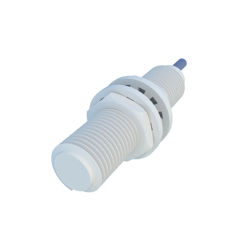
In contrast, a proximity switch (or proximity sensor) is a device that detects the presence or absence of a metallic (or sometimes non-metallic) object within its sensing range without physical contact. Its primary function is binary position detection: object present or object absent. Common types include inductive proximity switches (for metals), capacitive (for metals and non-metals), and ultrasonic. An inductive proximity switch, the most relevant for comparison in metallic sensing, generates an oscillating electromagnetic field from its face. When a metallic target enters this field, it causes a change in the oscillation amplitude, which is detected by the sensor's internal circuit, triggering a solid-state switch. Its output is typically a simple ON/OFF DC signal. Proximity switches are used for tasks like part detection on an assembly line, limit switching, counting objects, or verifying the position of a cylinder rod. They care about the presence of an object at a specific point, not the speed of a rotating element.
The confusion between the two likely arises because a gear speed sensor can be viewed as a specialized application of proximity sensing—it detects the passing of each gear tooth. However, the design intent and signal processing are distinct. A standard inductive proximity switch could theoretically detect gear teeth, but it is not optimized for this. Its output signal might not be clean or fast enough at high speeds, and it lacks the magnetic circuit design to generate a strong, consistent signal from the small, fast-changing air gap presented by a rotating gear. A dedicated gear speed sensor is engineered for this dynamic environment, providing a reliable signal even with variations in gear runout, speed, and temperature.
Key technical differences further highlight their separation:
1. Output Signal: A gear sensor provides an analog AC waveform (in its raw form) or a digital pulse train whose frequency is the key parameter. A proximity switch provides a discrete DC voltage signal (e.g., 24V DC ON, 0V DC OFF).
2. Measurement Target: Gear sensors require a ferromagnetic, toothed target. Proximity switches can be specified for various target materials.
3. Sensing Distance: Gear sensors typically require a very small, precise air gap (e.g., 0.5mm to 1.5mm). Proximity switches have a defined nominal sensing range (e.g., 5mm, 10mm) and are less sensitive to exact gap distance within that range for simple presence detection.
4. Dynamic Response: Gear sensors are built for high-frequency response, capable of tracking very high RPMs. The switching frequency of a standard proximity switch, while high, is a fixed specification (e.g., 1 kHz) and may be insufficient for high-speed rotational sensing.
5. Installation & Alignment: Gear sensors often require more precise radial and axial alignment to the gear. Proximity switch alignment is generally less critical for basic presence detection.
In summary, select a gear speed sensor when the primary requirement is to measure rotational speed or derive position information from a rotating toothed wheel. Choose a proximity switch when the requirement is to detect the presence or absence of an object at a specific location. Using the wrong sensor can lead to unreliable operation, signal errors, and system failure. For instance, attempting to use a standard proximity switch to accurately measure the speed of