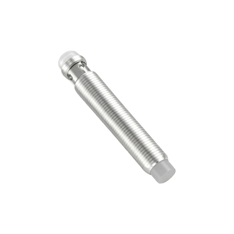
In industrial automation and control systems, proximity sensors play a critical role in detecting the presence or absence of objects without physical contact. Wiring these sensors in series is a common practice to optimize control logic, reduce wiring complexity, and enhance safety in machinery operations. This guide provides a detailed, step-by-step approach to connecting proximity sensors in series, adhering to standard electrical engineering principles and safety protocols.
Understanding the basics of proximity sensors is essential before attempting series wiring. Proximity sensors are typically categorized by their sensing technology: inductive, capacitive, or photoelectric. Inductive sensors, for instance, detect metallic objects and are widely used in manufacturing environments. Most industrial proximity sensors operate on DC or AC power supplies, with common voltage ranges being 10-30V DC or 20-250V AC. They feature output types such as NPN (sinking) or PNP (sourcing), which determine how they interface with controllers like PLCs (Programmable Logic Controllers). When wiring in series, it is crucial to ensure all sensors share the same output type and voltage rating to prevent malfunctions or damage.
The primary objective of wiring proximity sensors in series is to create a logical AND condition in a circuit. In this configuration, all sensors must be activated (i.e., detect an object) to complete the circuit and trigger a downstream action, such as energizing a relay or sending a signal to a PLC. This setup is particularly useful in safety-critical applications, like machine guarding or sequential process control, where multiple conditions must be met before operation proceeds. For example, in an automated assembly line, a series of sensors might verify that a workpiece is correctly positioned at each station before initiating the next step.
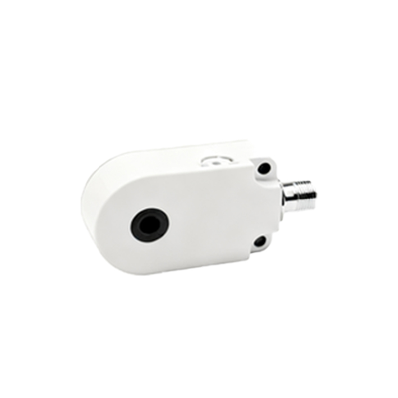
To wire proximity sensors in series, follow these technical steps. First, de-energize the power supply and verify zero voltage using a multimeter to ensure electrical safety. Identify the sensor terminals: typically, proximity sensors have three wires—brown (positive), blue (negative), and black (output). For DC sensors, connect the brown wires of all sensors to the positive terminal of the power supply. Then, link the blue wires to the negative terminal. The key to series wiring lies in connecting the output wires. Take the black output wire of the first sensor and connect it to the positive input of the second sensor’s load (e.g., a relay coil). Continue this pattern: the output of the second sensor connects to the input of the third, and so on. The final sensor’s output should be linked to the control device, such as a PLC input module. Ensure all connections are secure using appropriate wire gauges and terminals to avoid voltage drops or loose contacts.
Considerations for series wiring include voltage drop and current limitations. Since sensors are connected sequentially, the total voltage drop across the circuit increases with each added sensor. Calculate the cumulative voltage drop based on each sensor’s internal resistance and the load current. Exceeding the power supply’s voltage capacity can lead to unreliable sensor operation or failure. Additionally, check the maximum current rating of the sensors and the load to prevent overheating. For instance, if each sensor draws 20mA and the load requires 100mA, ensure the power supply can deliver at least 120mA. Using a regulated power supply with adequate headroom is recommended to maintain stability.
Troubleshooting common issues in series-wired proximity sensor circuits involves systematic testing. If the circuit fails to activate, use a multimeter to measure voltage at each sensor output when triggered. A lack of voltage at a specific point indicates a faulty sensor or connection. Also, verify that all sensors are correctly aligned with their target objects, as misalignment can cause false readings. In environments with electrical noise, such as near motors or welders, shield sensor cables and use ferrite cores to prevent interference. Regular maintenance, including cleaning sensor faces and inspecting wiring integrity, helps ensure long-term reliability.
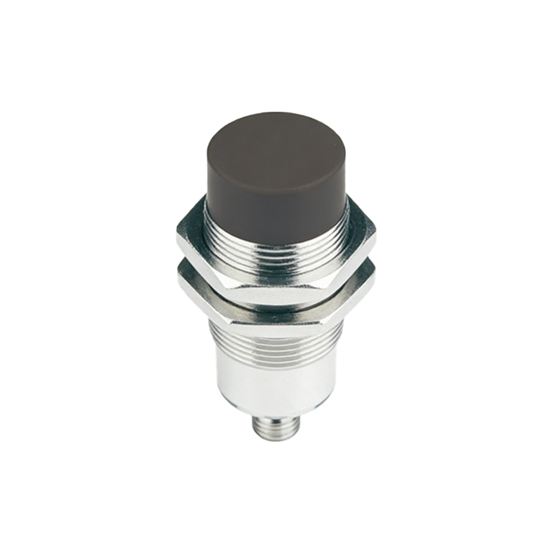
Advanced applications of series wiring include integrating sensors with safety relays or PLCs for complex automation tasks. For example, in a robotic cell, multiple proximity sensors can be wired in series to form a safety loop that halts the robot if any sensor detects an intrusion. When interfacing with PLCs, configure the input module to recognize the series circuit as a single digital input, simplifying programming logic. Always refer to manufacturer datasheets for specific wiring diagrams and specifications, as variations exist between sensor models and brands.
In summary, wiring proximity sensors in series is a practical method for creating interdependent detection systems in industrial settings. By following standardized procedures and accounting for electrical parameters, engineers can enhance system safety and efficiency. This approach aligns with industry best practices, such as those outlined in IEC 60947-5-2 for proximity sensor standards, ensuring compliance and operational excellence. As automation evolves, mastering such wiring techniques remains fundamental