Metal proximity sensors are fundamental components in modern industrial automation, renowned for their non-contact detection, durability, and reliability. However, a common performance issue that engineers and maintenance personnel encounter is slow sensor response. This lag can disrupt timing sequences, cause production bottlenecks, and lead to quality control problems. Understanding the root causes of this sluggish response is crucial for effective troubleshooting and maintaining optimal system performance. The reasons for slow response are multifaceted, often stemming from environmental factors, electrical issues, mechanical setup, or the inherent limitations of the sensor technology itself.
One primary category of causes is environmental interference and contamination. Metal proximity sensors operate by generating an electromagnetic field. The presence of conductive or magnetic materials near the active sensing face can distort this field. For instance, metal chips, dust, or even other machinery in close proximity can create a parasitic effect, causing the sensor to "see" a target prematurely or linger in a detected state. Furthermore, buildup of non-conductive contaminants like grease, oil, or thick paint on the sensor face can physically dampen the electromagnetic field, reducing its effective range and slowing down the detection event as the target must come closer to trigger a reliable signal. In harsh environments, sensors not rated for such conditions may experience internal condensation or corrosion, degrading electronic components and response times.
Electrical configuration and supply issues are another critical area. Every proximity sensor has a specified switching frequency, measured in Hertz (Hz), which defines its maximum number of detection cycles per second. Using a sensor with a low switching frequency (e.g., 10 Hz) in a high-speed application will inevitably result in perceived slowness, as the sensor physically cannot update its output state fast enough. The power supply quality is equally important. Voltage drops, ripple, or electrical noise on the supply lines can destabilize the sensor's internal oscillator and evaluation circuitry. Sensors connected to long cables without proper shielding are particularly susceptible to electromagnetic interference (EMI) from motors, frequency drives, or welding equipment, which can induce false signals or cause the output to oscillate slowly between states. Incorrect load matching, such as connecting a load that draws current near the sensor's maximum switching capacity, can also thermally stress the output stage and slow its operation.
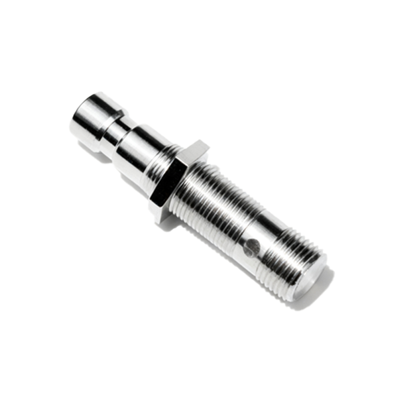
Mechanical and installation factors frequently contribute to response delays. The most straightforward issue is incorrect mounting. If the sensor is not aligned properly with the target—be it misaligned, mounted at an angle, or with an excessive air gap—the effective sensing distance is reduced. The sensor may only trigger when the target is very close, which in a fast-moving process translates to a late signal. The characteristics of the target itself are paramount. The sensor's rated sensing distance is typically defined for a standard mild steel square of a specific size. Smaller targets, targets made of non-ferrous metals like aluminum or copper (which have lower permeability), or irregularly shaped targets will reduce the effective sensing distance. This requires the target to travel further into the field to achieve the necessary trigger threshold, again causing a delayed response relative to the machine cycle.
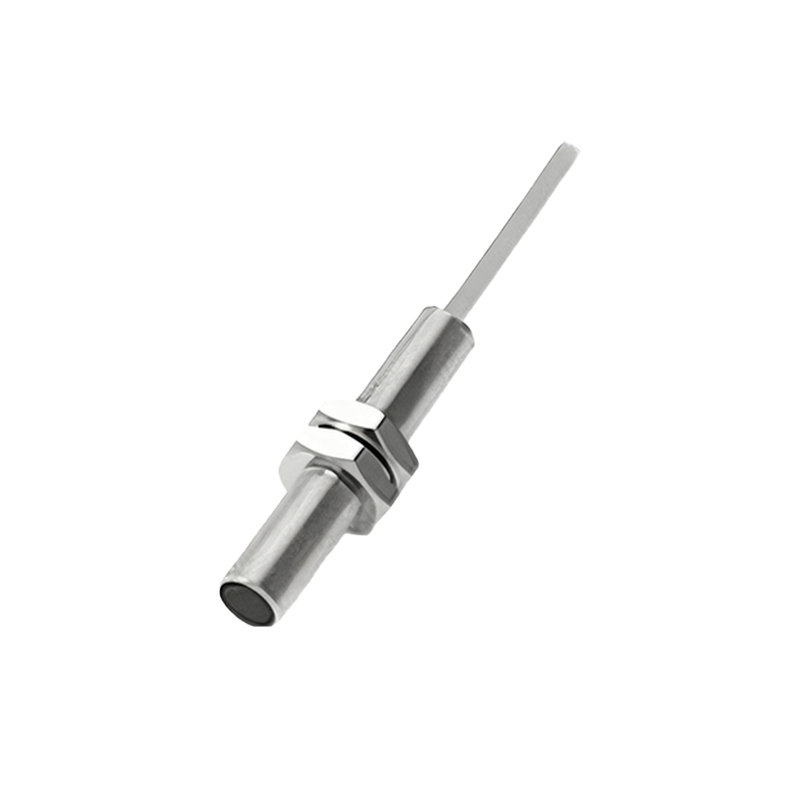
Finally, the inherent technology of the sensor plays a role. Inductive proximity sensors, the most common type for metal detection, have an internal oscillator, coil, and signal evaluation circuit. The time between the target entering the sensing field and the solid-state output switching is called the response time. This is a fixed specification (e.g., 0.5ms, 2ms, 10ms). While usually fast, in ultra-high-speed applications, even a few milliseconds matter. Furthermore, some sensors incorporate output delay functions (ON-delay, OFF-delay) or damping filters to suppress electrical noise. If these features are accidentally enabled or configured with long delay times, they will intentionally slow the output response. Using a sensor with a analog current/voltage output (4-20mA, 0-10V) instead of a discrete switch will also introduce conversion and processing latency compared to a simple digital PNP/NPN signal.
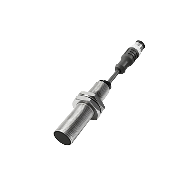
Addressing slow response requires a systematic approach. Begin by verifying the sensor's specifications against the application requirements for switching frequency, sensing distance, and target material. Inspect the installation for correct alignment, gap, and environmental contaminants. Check electrical connections for tightness, ensure a stable and clean power supply, and verify that cables are shielded and routed away from noise sources. Consult the datasheet to disable any programmable delay functions. Often, upgrading to a sensor with a higher switching frequency, a longer nominal sensing distance to account for target factors, or a more robust housing rating (IP67/IP69K) for the environment resolves the issue. Regular preventive maintenance, including cleaning and electrical checks, is essential to prevent the gradual degradation that leads to slow response over time.