Proximity switch sensors, as non-contact detection devices, have become indispensable components in modern industrial control systems. Their core function is to detect the presence or absence of a target object without physical contact, generating a corresponding electrical signal. The true intelligence and reliability of these sensors, however, are realized through their integrated or externally connected logic circuits. This article delves into the design principles, common configurations, and practical applications of logic circuits for inductive, capacitive, and photoelectric proximity sensors.
The fundamental operation of a proximity sensor involves the conversion of a physical detection event into a clean electrical signal, typically a change in voltage state (e.g., from 24V DC to 0V, or vice-versa, for a PNP or NPN output). This raw signal is often insufficient for complex control tasks. Logic circuits process this signal to implement functions such as timing, latching, counting, sequencing, and interlocking. The most basic logic element used is the transistor, which acts as a solid-state switch controlled by the sensor's internal oscillator or sensing element.
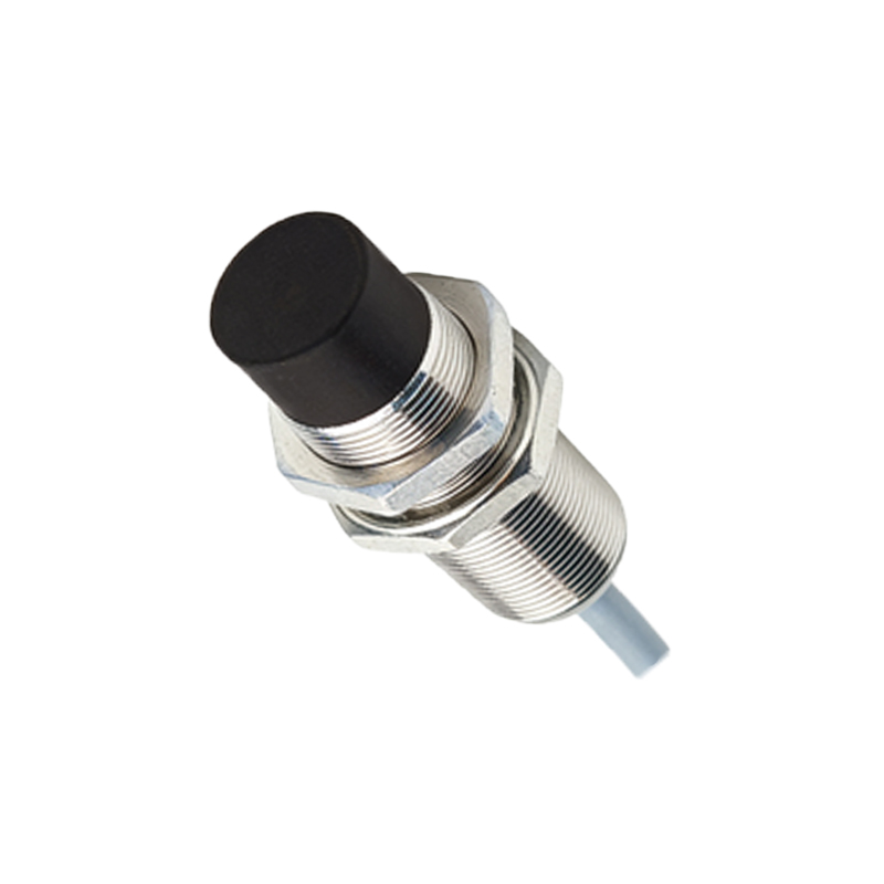
A standard three-wire DC sensor (PNP or NNP) incorporates a simple logic output stage. For a PNP (sourcing) sensor, the output transistor switches the load to the positive supply voltage. The logic here is simple: target present = output HIGH (supply voltage); target absent = output OPEN (or LOW through a pull-down resistor). Complementary logic applies to NPN (sinking) sensors. This built-in circuitry provides a robust digital signal compatible with Programmable Logic Controller (PLC) input modules.
For more advanced functionality, discrete logic ICs or small programmable devices are employed. Common applications include:
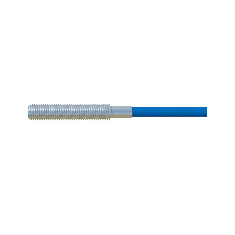
1. Timing Functions: Using monostable multivibrators (like the 555 timer) or digital timers to create On-Delay or Off-Delay. For instance, a sensor detecting a part on a conveyor might trigger a timer that keeps a solenoid activated for a precise 2-second interval after the part passes.
2. Latching (Memory) Circuits: Utilizing SR flip-flops or sealed relays to maintain an output state even after the target moves away. This is crucial in applications like safety guarding; once a guard door is opened (sensor triggered), the machine remains latched in a stopped state until a manual reset is performed.
3. Counting and Sequencing: Employing digital counters (e.g., CD4026) incremented by sensor pulses to count objects. Combined with decoders and other logic gates, this can create sequences: "After counting 10 items, activate the diverter arm for 1 second."
4. Window Comparators and Analog Processing: For analog-output sensors that provide a distance-proportional signal, comparator circuits define upper and lower thresholds. The logic output activates only when the signal is within this "window," useful for sorting objects by size or checking fill levels.
5. Interlocking and Safety: Using multiple sensors with AND/OR logic gates to ensure safe machine operation. An AND gate might require two hand buttons to be pressed simultaneously (by two sensors) before a press cycle starts, preventing hand-trapping.
Noise immunity is a critical design consideration. Industrial environments are rich in electromagnetic interference (EMI) from motors, welders, and power lines. Best practices include:
Using shielded cables for sensor connections.
Incorporating RC filter networks at logic inputs to suppress transient spikes.
Employing Schmitt trigger inputs on logic gates to provide hysteresis, ensuring a clean switch despite slow-moving or vibrating targets.
Ensuring proper grounding: separating logic ground (0V) from noisy earth grounds and using a single-point ground reference.
The rise of smart sensors with IO-Link, AS-i, or Profinet interfaces has integrated complex logic into the sensor head or the network master. These sensors can parameterize timing, counting, and logic functions (like AND/OR) directly via software, reducing the need for external hardware logic circuits. However, the underlying electronic principles remain valid, and for many cost-sensitive or high-speed applications, discrete logic circuits offer unmatched simplicity and reliability.
In conclusion, the logic circuit is the brain that translates the simple "detect/no-detect" signal of a proximity switch into actionable, intelligent control commands. A deep understanding of both digital logic fundamentals and the harsh realities of the industrial electrical environment is essential for designing robust, fail-safe sensor systems. Whether implemented with discrete components, dedicated timer/counter modules, or within smart sensor firmware, these logic functions form the bedrock of automated material handling, packaging, assembly, and safety systems.