Proximity sensors are essential components in industrial automation, providing non-contact detection of objects. Understanding their wiring is crucial for proper installation, troubleshooting, and system integration. This comprehensive guide details wiring diagrams for various proximity sensor types, including inductive, capacitive, and ultrasonic sensors, following standard industrial practices and electrical codes.
Inductive proximity sensors, commonly used for metal detection, typically have three or four wires. A standard 3-wire DC sensor includes brown (positive), blue (negative), and black (output) wires. The brown wire connects to the DC power supply positive terminal, usually 10-30V DC. The blue wire connects to the DC common or negative terminal. The black wire is the switched output, connecting to the PLC input or relay. For 4-wire sensors, the additional wire is often a second output (e.g., white wire for complementary output). Wiring diagrams show that shielded cables are recommended for noise reduction, with the shield grounded at one end only.
Capacitive proximity sensors, detecting both metallic and non-metallic materials, share similar wiring configurations but often include sensitivity adjustment. A typical diagram illustrates connections for normally open (NO) and normally closed (NC) output modes. The power terminals connect similarly to inductive sensors, while the output may be NPN (sinking) or PNP (sourcing). In NPN wiring, the load is connected between the output and positive supply; in PNP, between output and negative. Diagrams emphasize keeping sensor cables away from high-voltage lines to prevent interference.
Ultrasonic sensors, used for distance measurement, generally have four wires: brown (V+), blue (0V), black (output), and white (analog or configuration). Wiring diagrams detail connections for discrete and analog outputs. For example, in a 2-wire AC ultrasonic sensor, wiring involves series connection with the load to the AC line, requiring careful attention to voltage ratings. Diagrams include symbols for emitter and receiver alignment, with notes on avoiding obstacles in the sensing path.
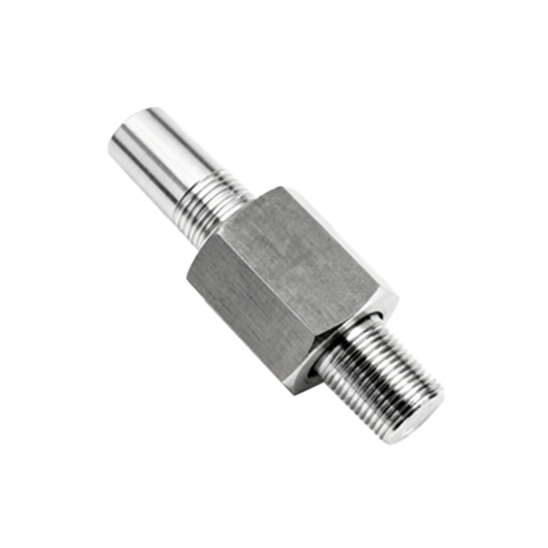
Two-wire AC proximity sensors simplify wiring by combining power and output in one loop. Diagrams show direct series connection with the load to the AC source (e.g., 120V AC). A critical note is the minimum load current requirement to keep the sensor active, often specified as 5mA. These sensors are commonly used in conveyor systems, with diagrams illustrating typical setups with indicator lights and control relays.
For network-integrated sensors, such as IO-Link models, wiring diagrams include communication lines. A standard IO-Link sensor has four pins: L+ (24V), C/Q (communication), L- (0V), and OUT (standard digital output). Diagrams show connections to an IO-Link master, with color-coded cables (e.g., black for L+, blue for L-, white for C/Q). Shielding and cable length limits (up to 20m) are highlighted to ensure data integrity.
Safety-rated proximity sensors, like those with SIL or PL ratings, have specific wiring requirements. Diagrams include dual-channel outputs with cross-monitoring, often showing connections to safety relays or PLCs. For example, a safety sensor with OSSD outputs (Output Signal Switching Devices) wires each output to separate safety controller inputs. Diagrams emphasize using certified cables and secure grounding to meet safety standards.
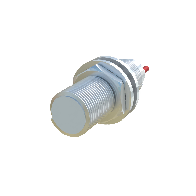
In complex systems, multiple sensors connect to a single power supply. Diagrams illustrate parallel wiring for common power distribution, with fuses or circuit breakers for each branch. For instance, a 24V DC supply powers ten inductive sensors, each fused at 100mA. Cable sizing charts are included, recommending 18 AWG for runs under 50 feet. Diagrams also show terminal block arrangements in control panels, labeling each wire for easy maintenance.
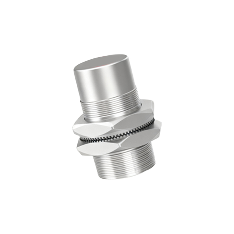
Troubleshooting sections in wiring guides often include diagnostic diagrams. For a malfunctioning sensor, diagrams show how to use a multimeter to check voltage at terminals, test output switching, and verify shield continuity. Common issues like reverse polarity, overload, or short circuits are depicted with schematic symbols, such as a crossed wire for a short.
Finally, environmental considerations affect wiring. Diagrams for waterproof sensors (IP67 rating) detail gland connectors and sealings, while high-temperature models show heat-resistant cable types. Always refer to manufacturer datasheets for exact pinouts and specifications, as colors and functions may vary by brand. Proper wiring ensures reliable operation, reduces downtime, and enhances system safety in industrial applications.