Proximity sensors are indispensable components in modern industrial automation, providing non-contact detection of metallic and, in some cases, non-metallic objects. Their reliability, long operational life, and fast response time make them superior to mechanical limit switches in countless applications. However, their correct integration into a control system hinges on proper wiring. This article provides clear, practical wiring diagram examples for the most common types of proximity sensors, adhering to standard industrial practices.
Understanding the Core: Sensor Output Types
Before examining diagrams, one must identify the sensor's output configuration, as this dictates the wiring. The two primary types are:
1. PNP (Sourcing): The sensor's output wire switches the positive voltage (+V) to the load. When active, it "sources" current to the load.
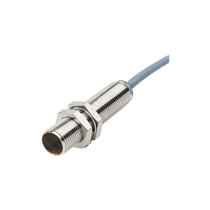
2. NPN (Sinking): The sensor's output wire switches the negative voltage (0V or common) to the load. When active, it "sinks" current from the load into itself.
A third wire, the common or ground, is always present. Many modern sensors are configurable as PNP or NPN.
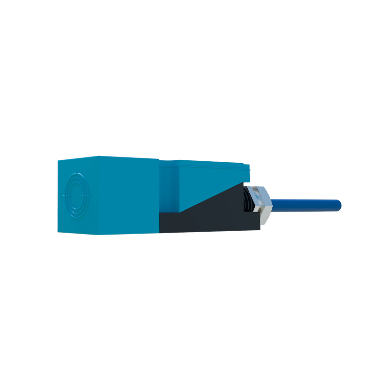
Wiring to a Programmable Logic Controller (PLC) Digital Input
This is the most frequent application. PLC digital input cards are typically designed as either sinking (common to +V) or sourcing (common to 0V). The sensor output must be chosen to match.
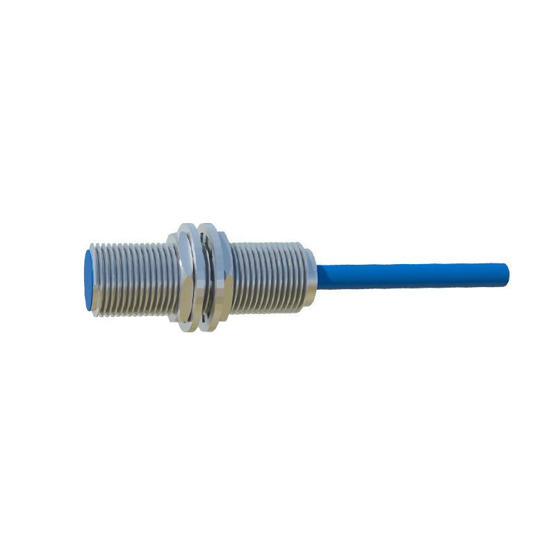
Example 1: PNP Sensor to a Sinking PLC Input.
This is a classic and compatible pairing. The PLC input card's common terminal is connected to the positive supply (+24VDC). The sensor's brown wire (+V) connects to the +24VDC supply. The sensor's blue wire (0V) connects to the power supply common. The sensor's black wire (output) connects directly to the PLC's input terminal. When the sensor detects an object, it sources +24VDC to the PLC input, completing the circuit through the card's internal electronics to its common, signaling an ON state.
Example 2: NPN Sensor to a Sourcing PLC Input.
This is the complementary pair. The PLC input card's common terminal is connected to the 0V/common. The sensor's brown wire (+V) and blue wire (0V) are connected to the power supply as usual. The sensor's black wire (output) connects to the PLC input terminal. When active, the NPN sensor sinks current, connecting the PLC input to 0V. Current flows from the PLC's internal supply, through its input circuit, out the input terminal, into the sensor's output, and to 0V, signaling an ON state.
Mismatching PNP and NPN with the PLC will result in the input never activating.
Wiring to a Relay or Contactor Coil
For directly controlling small loads like relay coils, the sensor acts as the switching element.
Example 3: PNP Sensor Driving a Relay.
Connect the +24VDC supply to one side of the relay coil. Connect the other side of the relay coil to the black (output) wire of the PNP sensor. Connect the sensor's blue wire to 0V and the brown wire to +24VDC. A free-wheeling diode (cathode to + side) across the relay coil is crucial to suppress voltage spikes. When the sensor activates, it completes the circuit from +24V, through the coil, through the sensor, to 0V, energizing the relay.
Example 4: NPN Sensor Driving a Relay.
Connect the relay coil to the +24VDC supply. Connect the sensor's brown wire to +24VDC and blue wire to 0V. Connect the black (output) wire to the other side of the relay coil. The free-wheeling diode remains essential. Here, when the NPN sensor activates, it connects the relay coil side to 0V, allowing current to flow from +24V, through the coil, through the sensor, to 0V.
Wiring 3-Wire Sensors in Series or Parallel
Sometimes, logic functions are needed without a PLC.
Example 5: Two PNP Sensors in Series (AND Logic).
To have an output only when both Sensor A AND Sensor B detect an object, wire them in series. Connect +24V to Sensor A's brown wire. Connect Sensor A's black wire to Sensor B's brown wire. Connect Sensor B's black wire to the load (e.g., a relay coil). Connect the other side of the load to 0V. Connect both sensors' blue wires to