In industrial automation and control systems, proximity sensors are indispensable components for detecting the presence or absence of objects without physical contact. Among the various feedback mechanisms integrated into these sensors, the red LED indicator plays a critical role in providing real-time operational status. This article delves into the significance, functionality, and troubleshooting aspects of the red LED on proximity sensors, tailored for electrical engineers and maintenance professionals.
When a proximity sensor is powered and functioning correctly, the red LED typically illuminates to signal that the sensor is active and ready to detect targets within its sensing range. In many models, especially inductive and capacitive types, the LED lights up steadily when the sensor is in a "normal" state—meaning it is energized but not yet triggered by an object. Upon detection, the LED may blink or turn off, depending on the sensor's design and configuration. For instance, in a normally open (NO) sensor, the LED might extinguish when an object is detected, indicating a change in output state. Conversely, in a normally closed (NC) sensor, the LED could remain lit or flash to denote activation. This visual cue is essential for quick diagnostics during installation and operation, allowing engineers to verify sensor responsiveness without relying solely on control system feedback.
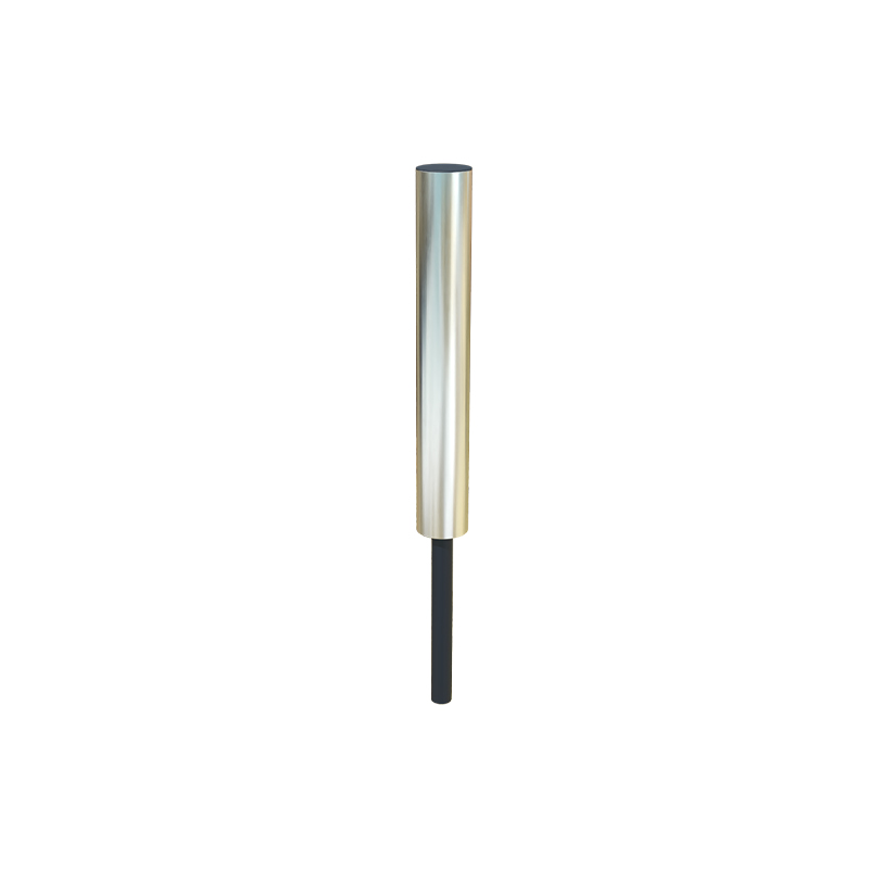
The red LED serves multiple purposes beyond basic status indication. First, it aids in alignment and setup. During installation, technicians can use the LED to fine-tune the sensor's position relative to the target. By observing when the LED changes state, they can ensure optimal sensing distance and avoid false triggers. Second, it facilitates troubleshooting. A malfunctioning sensor often exhibits abnormal LED behavior—such as remaining off despite power supply, flickering erratically, or staying on continuously without response to targets. Common issues leading to these symptoms include wiring errors, voltage fluctuations, sensor damage, or environmental factors like contamination or temperature extremes. For example, if the red LED fails to light up, check the power connections and ensure the voltage matches the sensor's specifications (e.g., 10-30 VDC for many industrial sensors). If the LED stays on permanently, it might indicate a short circuit, sensor saturation, or incorrect load connection.
In advanced proximity sensors, the red LED may incorporate flashing patterns to convey specific error codes or conditions. Manufacturers often design these patterns to indicate issues like overload, overheating, or sensing range deviations. Consulting the sensor's datasheet is crucial to interpret these signals accurately. Additionally, some sensors feature adjustable parameters via teach-in functions, where the LED guides users through programming steps by changing its illumination sequence.
From a technical perspective, the LED's behavior is tied to the sensor's internal circuitry. Proximity sensors operate based on electromagnetic fields (inductive), electrostatic fields (capacitive), or optical principles. The red LED is typically connected to the output stage or a dedicated diagnostic circuit. When the sensor detects a target, its output transistor switches, altering the current flow to both the load and the LED. This integration ensures that the LED reflects the actual output status, providing a reliable visual confirmation. However, engineers should note that in high-speed applications, the LED might not keep pace with rapid switching due to its inherent response time, so supplementary monitoring tools may be necessary.
Maintenance best practices emphasize regular inspection of the LED indicator as part of preventive routines. Dust, oil, or debris accumulation on the sensor face can attenuate sensing capability and affect LED visibility. Cleaning with appropriate solvents and verifying alignment during downtime can prevent operational disruptions. Moreover, when replacing sensors, ensure compatibility of LED indications across models to avoid confusion in existing systems.
In summary, the red LED on proximity sensors is a vital feature for ensuring efficient and reliable automation processes. Its intuitive feedback simplifies installation, enhances troubleshooting, and supports system integrity. By understanding its patterns and underlying mechanisms, electrical professionals can optimize sensor performance and minimize downtime in industrial environments. Always refer to manufacturer guidelines for specific details, as LED functions can vary by brand and application.