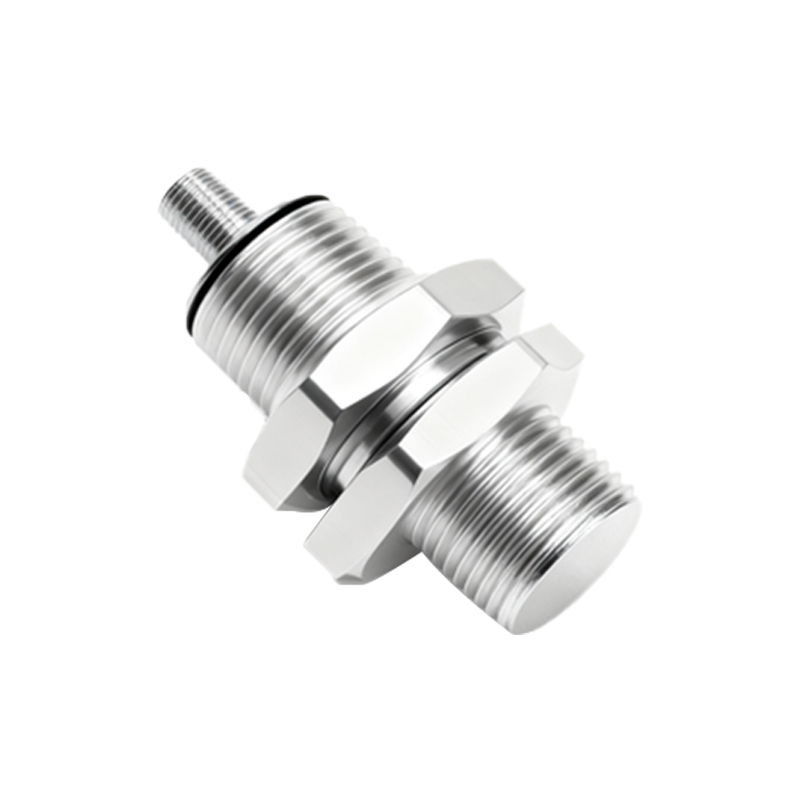
In industrial automation and control systems, proximity switches such as the LJ18A3 series are widely used for non-contact detection of metallic objects. These inductive sensors are valued for their reliability, durability, and ease of installation. However, a common challenge faced by engineers and technicians is the need to extend the sensor's wiring beyond its standard cable length to accommodate specific layout requirements. This article provides a detailed, step-by-step guide on how to properly extend the wiring of LJ18A3 proximity switches while maintaining signal integrity and ensuring long-term operational stability.
The standard LJ18A3 proximity switch typically comes with a fixed cable length, often around 2 meters. In many industrial setups—such as large conveyor systems, extensive machinery lines, or customized equipment—this length may be insufficient. Extending the wiring is not merely a matter of splicing additional cables; it requires careful consideration of electrical characteristics, environmental factors, and safety standards.
First, it is crucial to select the appropriate cable for extension. Use shielded, multi-core cables designed for industrial sensor applications. The cable should match or exceed the original specifications in terms of conductor size (typically 0.14 to 0.5 mm² for signal lines), insulation quality, and shielding effectiveness. Shielded cables help minimize electromagnetic interference (EMI) from nearby motors, frequency drives, or high-power lines, which can cause false triggering or signal degradation. For LJ18A3 sensors operating in harsh environments, choose cables with oil-resistant, waterproof, or UV-resistant jackets as needed.
Before starting the extension process, ensure the power supply to the sensor is completely disconnected. Follow lockout-tagout (LOTO) procedures to prevent accidental energization. Identify the sensor's wiring configuration: LJ18A3 sensors are available in both NPN (sinking) and PNP (sourcing) output types, typically with three wires—brown (positive), blue (negative), and black (signal output). Some models may include additional wires for diagnostic functions. Refer to the manufacturer's datasheet to confirm the pinout and voltage ratings (commonly 6-36V DC).
When splicing the cables, use proper techniques to ensure a secure and durable connection. Strip the insulation carefully to avoid nicking the conductors. For permanent installations, crimp connectors or solder joints are recommended. After joining the wires, insulate each connection individually with heat-shrink tubing or high-quality electrical tape. Maintain the shielding continuity by connecting the shield braid from both the original and extension cables. It is advisable to ground the shield at only one end (usually the control cabinet side) to prevent ground loops.
Once the physical connections are made, test the extended sensor before full deployment. Reconnect the power and verify the sensor's operation by detecting a target metal object at its specified sensing distance (for LJ18A3, this is typically 8 mm). Use a multimeter or an oscilloscope to check the output signal for stability and absence of noise. Pay attention to voltage drops over the extended length; for long runs (e.g., over 50 meters), consider using thicker gauge wires to reduce resistance.
In addition to electrical considerations, mechanical protection is vital. Route the extended cable through conduits, cable trays, or protective sleeves to safeguard against abrasion, crushing, or exposure to chemicals. Avoid running sensor cables parallel to high-voltage power lines; cross them at right angles if necessary. Secure the cable with clamps at regular intervals to prevent strain on the connections.
For applications requiring frequent reconfiguration or maintenance, using standardized connectors (such as M12 or M8 connectors) at the extension point can be beneficial. This allows for quick disconnection and replacement without rewiring. Ensure that any connectors used are rated for the environmental conditions (IP67 or higher for washdown areas).
Finally, document the modification. Update system schematics and maintenance logs to note the extended cable length, connection points, and any special considerations. This practice aids future troubleshooting and ensures compliance with industry standards.
Extending the wiring of LJ18A3 proximity switches is a straightforward task when done methodically. By adhering to best practices in cable selection, connection integrity, noise suppression, and mechanical protection, engineers can achieve reliable sensor performance over extended distances, thereby enhancing the flexibility and efficiency of industrial automation systems.