Proximity sensors are indispensable components in modern industrial automation, providing non-contact detection of metallic and non-metallic objects. Their reliability and longevity hinge significantly on correct installation and wiring. This guide delves into the standard wiring configurations for various types of proximity switches, focusing on 2-wire, 3-wire, and 4-wire systems, and provides essential considerations for optimal performance.
Understanding the fundamental types is crucial. Inductive proximity sensors detect metallic objects, while capacitive types can sense both metallic and non-metallic materials. Regardless of type, their electrical interface primarily falls into three categories.
1. 2-Wire Proximity Sensor Wiring
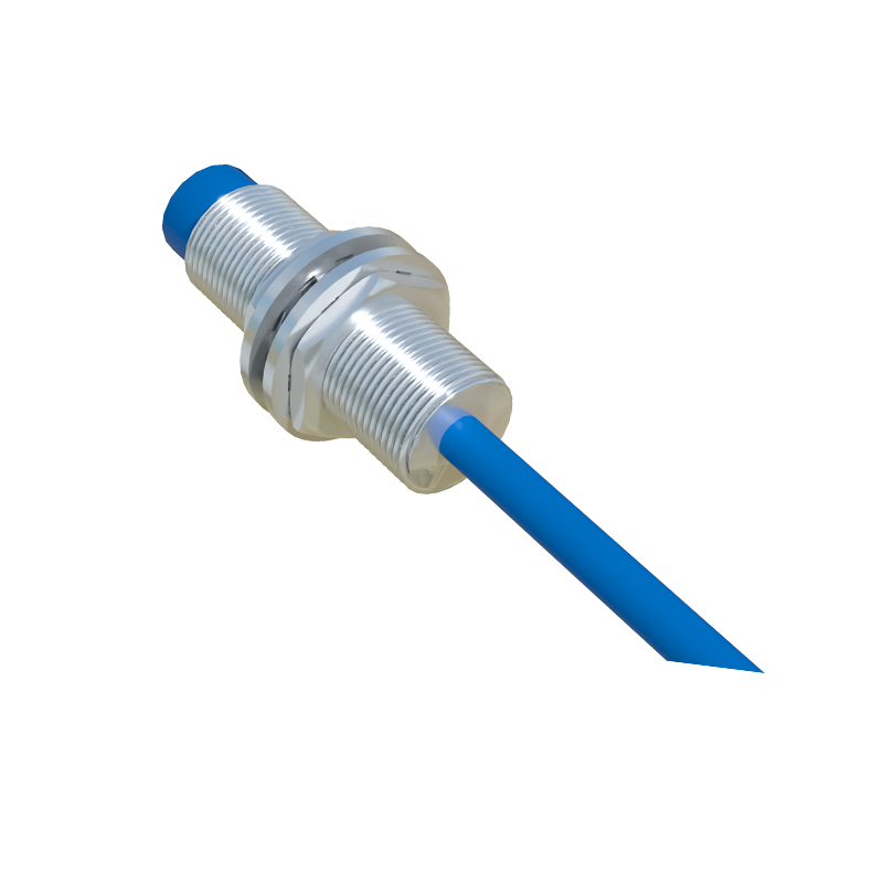
The 2-wire sensor is the simplest to connect, functionally similar to a mechanical switch. It is connected in series with the load. One wire is connected to the positive DC supply or one side of the AC supply, and the other wire is connected to the load. The other terminal of the load is then connected to the negative DC supply or the other side of the AC line.
Key Point: These sensors have a inherent voltage drop (typically 2-4V) and a small leakage current even when off. This must be considered when interfacing with PLCs or sensitive relays to avoid ghost signals. Always verify the sensor's compatibility with AC or DC supplies, as some are designed for specific voltage types.
2. 3-Wire Proximity Sensor Wiring
This is the most common configuration in DC systems, offering superior performance with separate supply and switching wires. The three wires are typically color-coded: Brown (or Red) for positive supply (+V), Blue for negative supply (0V or Common), and Black (or White) for the output signal.
Sourcing (PNP) Configuration: The output wire switches the positive voltage to the load. Wiring: Connect Brown to +V, Blue to 0V. The Black (output) wire connects to one terminal of the load (e.g., PLC input, relay coil). The other terminal of the load is connected to 0V. When activated, the sensor connects the load to +V, completing the circuit.
Sinking (NPN) Configuration: The output wire switches the negative or 0V connection to the load. Wiring: Connect Brown to +V, Blue to 0V. The Black (output) wire connects to one terminal of the load. The other terminal of the load is connected to +V. When activated, the sensor connects the load to 0V, completing the circuit.
Choosing between PNP and NPN is critical and depends on the control system's input card design. European systems often prefer PNP, while NPN is common elsewhere.
3. 4-Wire Proximity Sensor Wiring
A 4-wire sensor typically incorporates both a normally open (NO) and a normally closed (NC) output in one device, or sometimes two independent outputs (e.g., one PNP and one NPN). The wires are usually Brown (+V), Blue (0V), Black (NO output), and White (NC output).
Wiring: The supply is connected to Brown and Blue as usual. The Black and White wires provide complementary switching actions. Only one output is typically used at a time, depending on the required logic (failsafe high or failsafe low). This configuration offers great flexibility for control logic without external relays.
Critical Wiring Practices and Safety
1. Power Supply: Always use a stable, regulated DC power supply within the sensor's specified voltage range. Ripple and noise can cause erratic operation.
2. Load Compatibility: Ensure the sensor's maximum output current rating is not exceeded by the connected load (relay coil, PLC input, etc.). Use an intermediate relay for higher current loads.
3. Shielding and Conduit: In electrically noisy environments (near VFDs, large motors, welding equipment), use shielded cables. Connect the shield to ground at the control panel end only. Running cables in metal conduit provides additional protection.
4. Polarity: For DC sensors, observe correct polarity. Reverse polarity can permanently damage the device.
5. Short-Circuit Protection: While many sensors have built-in short-circuit protection, it is good practice to fuse the supply line according to the manufacturer's specifications.
6. Grounding: Properly ground the sensor housing if metallic, and ensure a clean, low-impedance earth ground for the system.
7. Initial Testing: Before final installation, perform a bench test. Power the sensor and verify its output state (LED indication) when a target is presented and removed.
Troubleshooting Common Issues
Sensor Not Triggering: Check