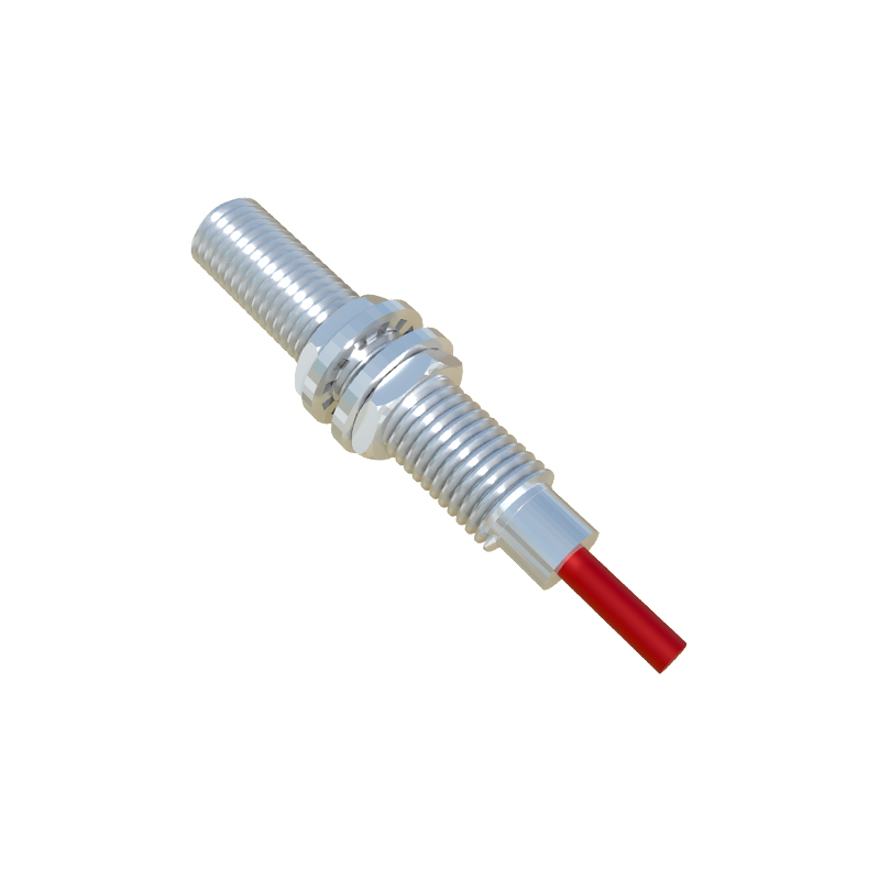
In industrial automation systems, proximity sensors play a critical role in detecting the presence or absence of objects without physical contact. To ensure their reliable operation, specialized testers are employed for diagnostics and calibration. This article delves into the schematic design and underlying principles of a proximity sensor tester, tailored for engineers and technicians in the electrical and automation fields.
A proximity sensor tester typically consists of several key components: a power supply unit, signal generation circuit, detection module, and display or output interface. The power supply unit provides stable DC voltage, often ranging from 12V to 24V, to mimic standard industrial sensor operating conditions. This unit includes regulators and filters to minimize noise, ensuring accurate testing. The signal generation circuit produces simulated target signals—such as metallic or non-metallic objects—that the sensor under test can detect. For inductive sensors, this involves generating electromagnetic fields; for capacitive sensors, it involves creating changes in capacitance.
The detection module is the core of the tester, analyzing the sensor's response. It measures parameters like output voltage, current, switching frequency, and response time. Advanced testers incorporate microcontrollers or programmable logic to compare these readings against predefined thresholds, identifying faults like drift, hysteresis, or false triggering. The display interface, often an LCD or LED panel, shows real-time data, while some models offer analog outputs or communication protocols (e.g., RS-485, Ethernet) for integration into larger diagnostic systems.
From a schematic perspective, the design emphasizes precision and robustness. For example, in testing inductive proximity sensors, the schematic includes an oscillator circuit that generates a high-frequency magnetic field. When a sensor is placed near the tester's coil, its internal oscillator's amplitude changes, detected by a demodulator and amplifier. The output is then fed into a comparator to determine if the sensor triggers correctly. Diodes and transistors are used for protection against reverse polarity and voltage spikes, common in industrial environments.
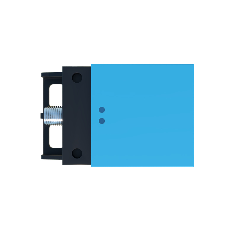
Key principles behind the tester involve electromagnetic induction for inductive sensors and dielectric variation for capacitive ones. Inductive sensors rely on eddy currents induced in metallic targets, altering the sensor's LC circuit resonance. The tester simulates this by adjusting the frequency and amplitude of its oscillator. Capacitive sensors detect changes in capacitance caused by non-metallic objects; the tester uses variable capacitors or simulated dielectric materials to replicate these conditions. Additionally, timing circuits ensure accurate measurement of response times, crucial for high-speed automation applications.
In practice, using such a tester involves connecting the sensor to the appropriate terminals, selecting the test mode (e.g., NPN or PNP output types), and observing the readings. Calibration features allow adjustment of sensitivity and threshold levels, matching specific sensor specifications. This not only aids in troubleshooting but also in preventive maintenance, reducing downtime in production lines.
Overall, a well-designed proximity sensor tester schematic balances simplicity with functionality, enabling efficient validation of sensor performance. As Industry 4.0 advances, these testers are evolving with digital interfaces and AI-driven diagnostics, yet the core principles remain rooted in fundamental electrical engineering. Engineers must consider factors like environmental interference, power stability, and compatibility with diverse sensor models when designing or selecting a tester. By understanding these schematics and principles, professionals can enhance system reliability and optimize automation processes.