Laser sensors are integral components in modern electrical and automation systems, and their representation in schematic diagrams is standardized for clarity and universal understanding. The symbols used for laser sensors are defined by international standards, primarily the IEC 60617 standard, which ensures consistency across engineering documentation worldwide.
A typical laser sensor symbol in an electrical schematic consists of a circle or a rectangle representing the sensor housing, with a specific internal graphic indicating its function. Inside the enclosure, a stylized depiction of laser beams is often shown as straight, parallel lines emanating from a point source, sometimes accompanied by a small triangle or arrow to denote directionality. This visual cue immediately distinguishes laser sensors from other optical or proximity sensors. The symbol may also include additional markings to specify the type of laser sensor, such as diffuse, retro-reflective, or through-beam variants. For instance, a through-beam laser sensor might be represented with two separate symbols—one for the transmitter and one for the receiver—connected by dashed lines indicating the laser beam path.
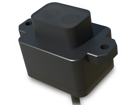
Electrical connections are critical in these symbols. Most laser sensor symbols include terminals for power supply, typically labeled as V+ and V- or L+ and L-, and output terminals for signal transmission. The output type, whether PNP (sourcing) or NPN (sinking), is often indicated near the output terminal with a small arrow or abbreviation. Some advanced symbols incorporate functional elements like timing diagrams or logic gates to represent programmable features such as adjustable sensing ranges or time-delay functions.
Understanding these symbols is essential for engineers and technicians during the design, installation, and troubleshooting phases. Misinterpreting a symbol can lead to incorrect wiring, system malfunctions, or safety hazards, especially given the precise nature of laser-based sensing. For example, confusing a diffuse laser sensor symbol with a retro-reflective one might result in improper alignment, affecting measurement accuracy in applications like object detection or distance monitoring.
In practice, schematic diagrams often include a legend or key explaining each symbol, but familiarity with standard representations enhances efficiency. When reviewing schematics, professionals should also note any manufacturer-specific annotations, as some companies add unique identifiers to their laser sensor symbols for enhanced functionality or compatibility notes. It is advisable to cross-reference symbols with the sensor’s datasheet to confirm electrical characteristics, such as voltage ratings and output current limits.

The evolution of laser technology has led to more complex symbols incorporating digital communication interfaces like IO-Link or Ethernet, represented by additional lines or icons within the symbol. These adaptations reflect the growing integration of smart sensors in Industry 4.0 environments, where laser sensors not only detect objects but also transmit data for analytics and control.
Overall, mastering laser sensor symbols contributes to safer and more efficient electrical system design. As automation expands, these symbols will continue to evolve, but their core principles—clarity, standardization, and accuracy—remain paramount for effective engineering communication.