In the realm of industrial automation and machine safety, proximity sensors are indispensable components. Among the various types available, the "Snail Eye" style proximity sensor, named for its distinctive lens shape resembling a snail's eye, has gained popularity for its reliable performance in detecting objects at close range. As a seasoned electrical engineer, understanding the precise activation and commissioning procedure for these sensors is crucial for ensuring system integrity and operational safety. This guide provides a comprehensive, step-by-step walkthrough on how to properly activate and configure a typical inductive Snail Eye proximity sensor.
Before initiating the activation process, a fundamental pre-commissioning check is mandatory. First, verify the sensor's specifications against the system requirements. Confirm the sensing distance, which for these compact sensors is typically short-range (e.g., 2mm to 5mm for inductive types). Ensure the housing material (often stainless steel) and the IP rating (commonly IP67) are suitable for the installation environment. Crucially, identify the electrical type: is it a DC 2-wire, DC 3-wire (NPN or PNP), or an AC model? The wiring and activation steps differ accordingly. Always consult the manufacturer's datasheet—this is your primary reference document.
The physical installation forms the foundation for correct operation. Mount the sensor securely using the appropriate hardware, ensuring it is aligned correctly with the target object. The sensing face must be parallel to the target surface for optimal performance. Maintain the specified nominal sensing distance (Sn), and account for any reduction factors for different target materials if not standard steel. Avoid mounting in areas with excessive vibration or where metal shavings or conductive dust could accumulate on the face, as this may cause false triggering.
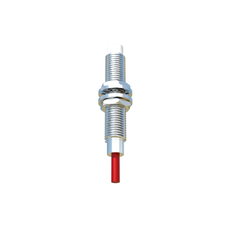
Wiring is the next critical phase. For a standard 3-wire DC sensor:
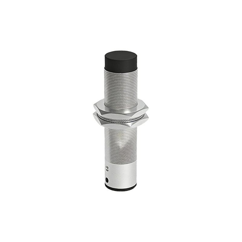
1. Power Supply: Connect the Brown wire (typically) to the positive DC voltage terminal (e.g., +24VDC) and the Blue wire to the negative/0V terminal. Adhere strictly to the voltage range specified (commonly 10-30VDC).
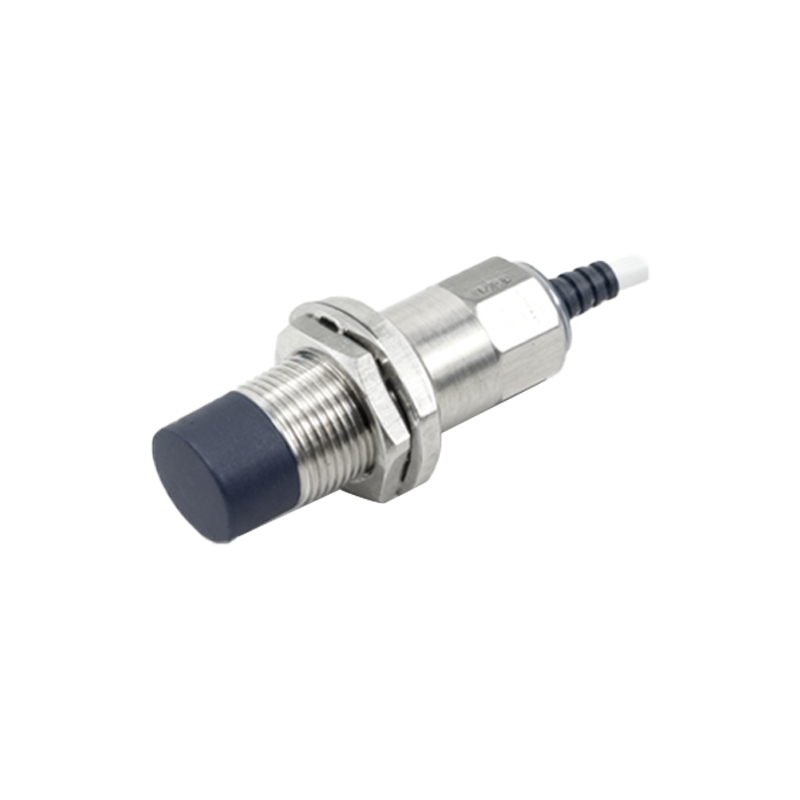
2. Load Connection: Connect the Black wire (the output signal) to your load (e.g., a PLC input module, a relay coil).
For an NPN (sinking) sensor, the Black wire is the switched negative output. The load is connected between the Black wire and +V.
For a PNP (sourcing) sensor, the Black wire is the switched positive output. The load is connected between the Black wire and 0V.
3. Shielding: If using a shielded cable, ground the shield at the control panel end only to prevent ground loops.
For 2-wire DC or AC sensors, the wiring integrates the load directly in series with the power lines. Always ensure the load current falls within the sensor's switching capacity.
Once wired, you can proceed to power on the system. Upon applying power, most Snail Eye sensors will have a small LED indicator light. A steady or blinking light often indicates power is present. However, this does not mean the sensor is correctly activated or tuned for its application.
Activation and Adjustment involves teaching the sensor its operational parameters. Many modern Snail Eye sensors feature a simple "teach-in" function for setting the switching point, especially useful in applications with non-standard targets or to compensate for installation tolerances. A common method is:
1. Place the standard target (a square of specified material and thickness) at the desired operating distance from the sensor face.
2. Press and hold the teach button (often a small recessed button on the body or accessed via a magnetic tool) until the LED changes behavior (e.g., flashes rapidly).
3. The sensor now stores this distance as its new switching point. Remove the target; the LED should turn off. Bring the target back within range; the LED should illuminate, and the output should switch.
If your sensor has a potentiometer for sensitivity adjustment, use a non-metallic screwdriver to fine-tune it. Rotate the pot slowly while observing the target at the limit of the required sensing range. Adjust until the sensor reliably detects the target and does not trigger on background interference.
Testing and Validation is non-negotiable. After activation, perform a full functional test.
1. Introduce the target object slowly into the sensing field. Observe the output state change on the sensor's LED and verify the corresponding reaction in your control system (PLC input indicator, relay actuation).
2. Check the repeatability by performing this action multiple times.
3. Test for false triggers by moving non-target materials (like your hand, plastic, or