Proximity sensors are essential components in modern automation, robotics, and consumer electronics, detecting the presence or absence of objects without physical contact. A critical aspect of integrating these sensors into any system is understanding their pinout—the arrangement and function of each electrical pin. This guide provides a comprehensive overview of proximity sensor pin configurations, typical wiring setups, and practical considerations for reliable operation.
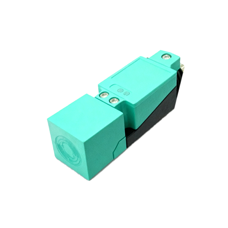
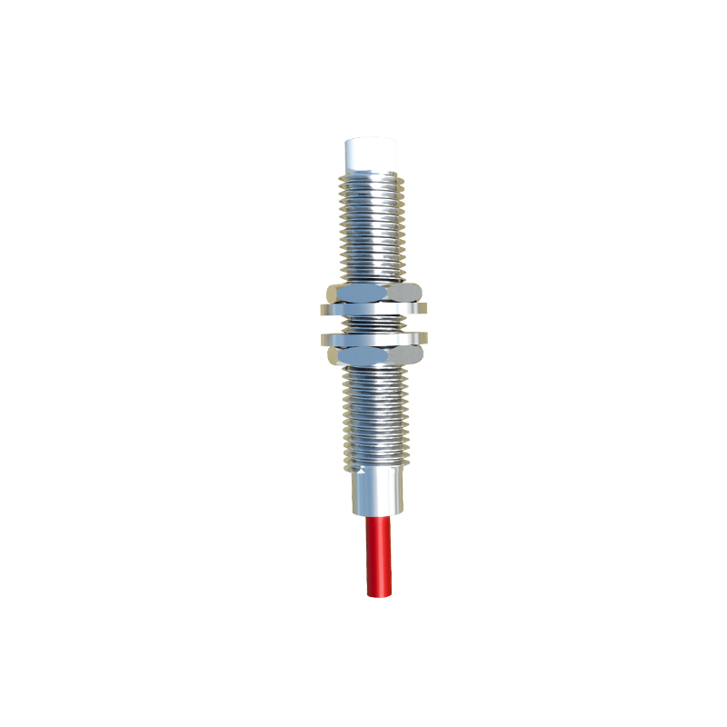
Most industrial and electronic proximity sensors feature a standardized set of pins, though the exact count and roles can vary by type (inductive, capacitive, or photoelectric) and output form (NPN, PNP, or analog). A common three-pin configuration includes power supply (Vcc), ground (GND), and output signal (OUT). For example, in a DC-powered inductive sensor, Vcc connects to the positive supply voltage (often 12-24V DC), GND to the negative or common terminal, and OUT provides a switching signal—high or low—based on object detection. Some sensors add a fourth pin for diagnostic or enable functions, while others integrate analog output pins for distance-proportional voltage or current signals.
Wiring these pins correctly is paramount. Incorrect connections can lead to sensor damage, erratic behavior, or system failure. Always refer to the manufacturer’s datasheet for the specific pinout diagram. For NPN-type sensors, the output pin sinks current to ground when active, commonly used in sinking input modules. PNP-type sensors source current from the positive supply, suitable for sourcing inputs. Mixed wiring can cause compatibility issues with controllers like PLCs or microcontrollers. Shielding and proper cable routing are also crucial, especially in environments with electromagnetic interference, to prevent false triggering.
Beyond basic connections, understanding pin functions enhances system design. Many sensors include pins for output inversion, sensitivity adjustment, or timer modes, accessible via configuration interfaces or additional wiring. For instance, a teach-in pin might allow reprogramming of the detection range without disassembly. In networked or smart sensors, communication pins (e.g., for IO-Link) enable data exchange beyond simple on/off signals, providing diagnostics, parameterization, and process values. These advanced features, however, require careful pin mapping and protocol adherence.
In practice, testing the pinout before full integration saves time and resources. Use a multimeter or oscilloscope to verify voltage levels and signal integrity under detection and non-detection states. For custom applications, breakout boards or adapter cables can simplify connections to development boards like Arduino or Raspberry Pi. Remember that environmental factors—such as temperature, humidity, or material composition of target objects—can affect sensor performance, even with perfect wiring. Regular maintenance, including pin inspection for corrosion or loose contacts, ensures long-term reliability.
Ultimately, mastering proximity sensor pinouts empowers engineers and hobbyists to build more robust and efficient systems. Whether you’re automating a production line, designing a smart device, or troubleshooting existing setups, a clear grasp of these connections reduces downtime and optimizes functionality. As sensor technology evolves, with miniaturization and increased intelligence, pinouts may grow more complex, but the fundamental principles of power, ground, and signal remain the cornerstone of successful implementation.