Building a laser sensor from scratch is an engaging project that combines optics, electronics, and programming. For electrical engineers, this hands-on endeavor offers practical insights into sensor design, signal processing, and system integration. This guide outlines the fundamental steps to create a basic laser-based proximity or detection sensor, suitable for applications like object detection, alignment, or distance measurement.
The core components include a laser diode module, a photodetector (such as a photodiode or phototransistor), a microcontroller (like an Arduino or Raspberry Pi), and supporting circuitry. Begin by selecting a low-power visible red laser diode (e.g., 650nm, 5mW) for safety and ease of alignment. The photodetector must be sensitive to the laser's wavelength; a silicon photodiode with a matching spectral response is ideal. To minimize ambient light interference, consider using a narrow-band optical filter or housing the detector in a darkened tube.
Circuit design focuses on converting light signals into measurable electrical outputs. For the laser driver, a constant current source circuit using an LM317 regulator or a dedicated laser driver IC ensures stable operation and prevents damage from current spikes. On the detection side, the photodiode typically operates in photovoltaic or photoconductive mode. A transimpedance amplifier (TIA) circuit, built with an operational amplifier like the LM358 or MCP6001, converts the photodiode's small current output into a voltage signal. Proper PCB layout—with short traces, grounding planes, and noise reduction capacitors—is crucial to maintain signal integrity.

Microcontroller programming enables real-time data processing. Connect the TIA output to an analog-to-digital converter (ADC) pin on the microcontroller. Write code to read voltage levels, set detection thresholds, and implement filtering algorithms (e.g., moving average) to distinguish the laser signal from noise. For distance sensing, time-of-flight or triangulation methods can be explored, though they require more advanced timing circuits or multiple detectors. Calibration involves adjusting the laser alignment and threshold values using known reference objects.
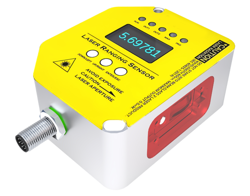
Testing and optimization are iterative processes. Use an oscilloscope to observe signal waveforms and identify issues like oscillation in the TIA or ambient light leakage. Enclose the sensor in a rigid casing to protect optical alignment from vibrations. Potential enhancements include adding modulation/demodulation techniques (e.g., pulsing the laser at a specific frequency) for improved noise immunity, integrating wireless communication modules for remote monitoring, or implementing lens systems to focus the laser beam.
Safety is paramount: always wear laser safety goggles, avoid pointing the laser at eyes or reflective surfaces, and adhere to local regulations on laser device usage. This project not only reinforces core engineering principles but also provides a customizable sensor platform for industrial automation, robotics, or research prototypes. With careful design and testing, a DIY laser sensor can achieve reliable performance comparable to commercial units, at a fraction of the cost.
Remember, experimentation is key—adjust component values, try different algorithms, and document each iteration to refine your design. The skills gained extend beyond sensors, fostering expertise in analog circuit design, embedded systems, and optoelectronics integration.