In modern industrial automation, integrating laser sensors with Programmable Logic Controllers (PLCs) is a critical task for achieving precise measurement, detection, and control. Laser sensors offer high accuracy, fast response times, and reliability in harsh environments, making them ideal for applications like object detection, positioning, and quality inspection. Connecting these sensors to a PLC involves several technical steps, from selecting the right components to configuring communication protocols. This guide provides a comprehensive overview of the process, tailored for electrical engineers and automation professionals.
First, ensure compatibility between the laser sensor and the PLC. Check the sensor’s output type—common options include analog (e.g., 4-20 mA or 0-10 V), digital (e.g., NPN/PNP switching), or serial communication (e.g., RS-485, Ethernet/IP). Analog outputs are suitable for continuous measurement, while digital outputs work for on/off detection. For PLCs, verify the input module specifications, such as voltage ranges and signal types. Mismatched signals can lead to errors or damage, so consult datasheets from manufacturers like Siemens, Allen-Bradley, or Omron.
Wiring is the next crucial step. For analog connections, connect the sensor’s output to the PLC’s analog input module. Use shielded cables to reduce electrical noise, especially in industrial settings with motors or high-frequency equipment. For digital connections, wire the sensor’s output to a digital input on the PLC. Ensure proper grounding to prevent interference and follow safety standards like IEC 61131. If using serial communication, connect via RS-485 or Ethernet cables, and set matching baud rates and parity settings. Always power the sensor separately if required, using a stable DC supply to avoid voltage drops.

PLC programming involves configuring the input channels to interpret sensor data. In ladder logic or structured text, map the sensor input to a memory address. For analog signals, scale the raw values (e.g., 0-4095 for a 12-bit ADC) to engineering units like millimeters or volts. Use PLC functions like SCALE in Siemens TIA Portal or Compute in Rockwell Studio 5000. For digital signals, trigger logic based on high/low states. Implement error handling for signal loss or out-of-range values to enhance system robustness. Testing is essential: simulate conditions with a test object and monitor PLC registers to verify accuracy.
Advanced setups may involve multiple sensors or network integration. For distributed systems, use industrial protocols like Profinet, EtherCAT, or Modbus TCP. Configure the PLC as a master device and sensors as slaves, ensuring proper IP addressing and data mapping. In applications requiring high-speed feedback, such as conveyor belt sorting, optimize scan cycles and use interrupt routines to minimize latency. Regular maintenance, including calibration and cable checks, ensures long-term reliability.
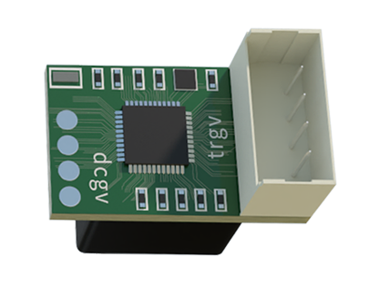
In summary, connecting laser sensors to PLCs requires attention to hardware compatibility, wiring practices, and software configuration. By following these steps, engineers can build efficient automation systems that leverage the precision of laser technology. As Industry 4.0 evolves, integrating smart sensors with PLCs will continue to drive innovation in manufacturing and beyond.