In industrial automation and control systems, proximity switches are indispensable components for non-contact detection of metallic or non-metallic objects. Among various wiring configurations, the 5-wire proximity switch stands out for its enhanced functionality and safety features, particularly in DC (Direct Current) applications. This guide delves into the technical details, wiring methodology, and practical considerations for implementing 5-wire DC proximity sensors, a staple in modern electrical engineering.
Understanding the five wires is fundamental. A standard 5-wire DC proximity switch typically comprises the following terminals:
1. Brown Wire (+V or L+): This is the positive supply wire. It must be connected to the positive terminal of the DC power source. The voltage range (e.g., 10-30V DC) is specified by the manufacturer and must be strictly adhered to.
2. Blue Wire (0V or M or L-): This is the negative or common wire. It connects to the negative terminal of the DC power source, completing the power circuit for the sensor's internal electronics.
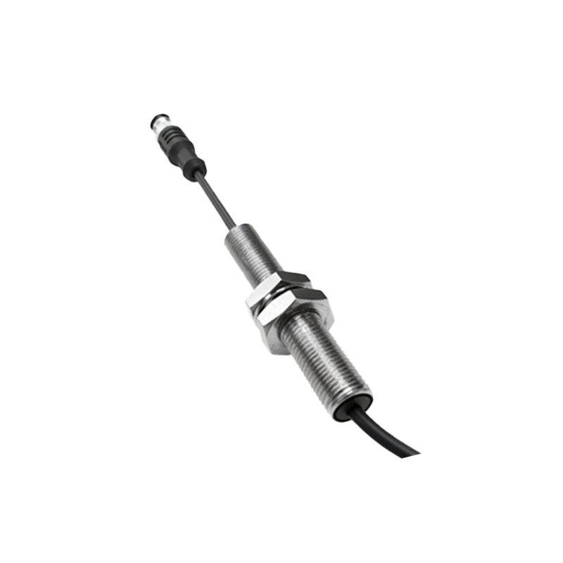
3. Black Wire (NO - Normally Open Output): This is one of the two switch output wires. In its normal, non-activated state (no target present), this circuit is open. When a target enters the sensing range, this switch closes, allowing current to flow.
4. White Wire (NC - Normally Closed Output): This is the complementary output wire. In its normal state, this circuit is closed. Upon detection of a target, this switch opens, interrupting the current flow.
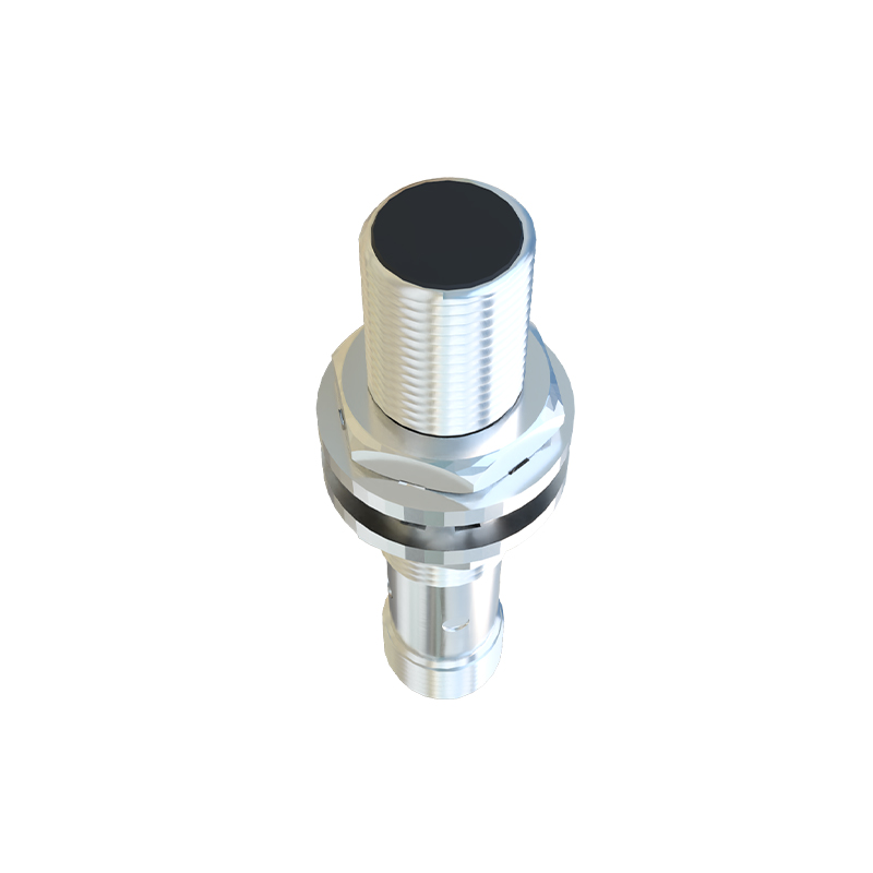
5. Black (or sometimes Gray) Wire (NO Output 2): Many 5-wire sensors provide a second, independent Normally Open output. This allows a single sensor to control two separate circuits or provide a redundant signal. It functions identically to the Black (NO) wire.
The primary advantage of the 5-wire configuration is the provision of both NO and NC contacts from a single device. This offers tremendous flexibility in control logic design. For instance, an NC output can be used for a safety-critical "stop" or "guard" circuit, where a broken wire or sensor failure (often mimicking an open circuit) causes a machine halt. Simultaneously, the NO output can be used for a standard "part present" signal to a Programmable Logic Controller (PLC) input module.
Wiring Procedure and Best Practices:
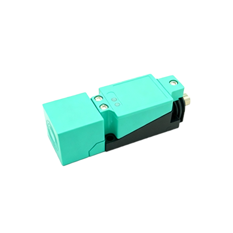
1. Power Supply: Always ensure a stable, regulated DC power supply matching the sensor's specifications. Connect the Brown wire to DC+ and the Blue wire to DC-.
2. Load Connection: The output wires (Black, White, and the second Black) are connected to the load. This load is typically the input of a PLC, a relay coil, or an indicator lamp. It is crucial to note that these are sourcing outputs. The sensor switches the positive supply to the load. Therefore, the other side of the load must be connected back to the DC- (Blue wire/0V).
Example for Black (NO) wire: DC+ (via Brown) -> Sensor Internal Switch -> Black Wire -> Load (e.g., PLC input X0) -> DC- (Blue).
3. Shield Wire: Many industrial proximity switches include an uninsulated braided shield or a dedicated drain wire. This should be grounded at one end only (usually at the control panel) to minimize electromagnetic interference (EMI) from motors or frequency drives.
4. Protection: Incorporate protective devices such as fuses or circuit breakers in the supply line. For inductive loads like relay coils, use a suppression diode or a varistor across the load to protect the sensor's solid-state output from voltage spikes.
5. Sensing Distance: Be mindful of the rated operating distance. Factors like target material, size, and installation environment (e.g., adjacent metal) can affect performance. Always refer to the sensor's datasheet for derating factors.
Diagnostics and Troubleshooting:
Most 5-wire sensors include an LED indicator. A steady light often indicates power, while a blinking or changed state indicates target detection. For output testing, a multimeter set to measure DC voltage is essential. With power applied and no target present, you should measure supply voltage between the White (NC) wire and Blue wire, and 0V between the Black (NO) wire and Blue wire. This state reverses when a valid target is presented to the sensing face.
In summary, the 5-wire proximity switch is a versatile and robust solution for complex sensing tasks. Its dual complementary outputs enable sophisticated and fail-safe control strategies, making it a preferred choice in safety interlock systems, material handling, and automated machinery. Proper