In industrial automation systems, the integration of proximity sensors with Programmable Logic Controllers (PLCs) is fundamental for reliable operation. A common and frustrating issue encountered by engineers and technicians is when a proximity sensor, after being correctly wired to a PLC input module, shows no response. The sensor may not trigger, or the PLC does not register the input signal change despite the target being within the sensing range. This guide provides a systematic, industry-standard approach to diagnosing and resolving this problem.
The first and most critical step is to verify the power supply. A proximity sensor requires a stable DC voltage to operate, typically 10-30V DC for most industrial models. Use a multimeter to measure the voltage between the positive (brown wire) and negative (blue wire) terminals at the sensor connector. Ensure the voltage is within the specified range and stable under load. A voltage drop or complete absence of power will render the sensor inoperative. Simultaneously, confirm that the PLC input module itself is powered correctly and that its common terminal (sourcing or sinking) is properly connected relative to the sensor's output type.
Next, meticulously inspect the wiring configuration. This is the most frequent source of failure. A three-wire DC sensor has three connections: positive (brown), negative (blue), and signal output (black). The output type—NPN (sinking) or PNP (sourcing)—must be compatible with the PLC input module. An NPN sensor switches the signal line to negative (0V), requiring a sinking PLC input (common connected to positive). A PNP sensor switches the signal line to positive, requiring a sourcing PLC input (common connected to 0V). A mismatch here will prevent signal detection. Check for loose connections, damaged cables, or incorrect termination at the sensor, junction box, and PLC terminal. Ensure the shield wire, if present, is grounded only at one end to prevent ground loops.
After confirming power and wiring, isolate the sensor for a standalone test. Temporarily disconnect the sensor's signal wire from the PLC input. Connect an LED indicator or a multimeter between the sensor's signal wire (black) and the negative supply line (blue). Actuate the sensor by bringing the target metal within its sensing range. For a PNP sensor, the LED should illuminate, or the multimeter should show the supply voltage when activated. For an NPN sensor, test between the signal wire and the positive supply. If the sensor functions correctly in this test, the issue lies downstream in the PLC system. If it fails, the sensor itself is likely faulty or incorrectly specified for the application (e.g., sensing range, target material, or environmental factors like temperature or contamination).
Assuming the sensor tests correctly, the focus shifts to the PLC. Check the specific input address on the PLC's diagnostic software or hardware indicators. Most PLC input modules have LED status lights for each channel that illuminate when an active input signal is detected. If the LED lights upon sensor activation but the PLC logic does not respond, the problem is within the software. Verify that the correct input address is used in the ladder logic or function block program. Check for any overriding forces, permanent logic states (like a seal-in instruction locking it out), or conflicts in the program that might be masking the input.
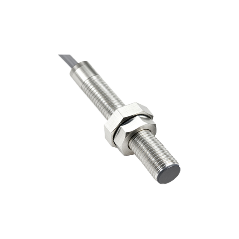
Environmental and application-specific factors must also be considered. Electrical noise from nearby motors, variable frequency drives (VFDs), or welding equipment can induce false signals or swamp the sensor's output. Ensure proper shielding, separation of power and signal cables, and the use of ferrite cores if necessary. Verify the sensor's sensing distance; the target must be well within the rated nominal range. For inductive sensors, ensure the target is a ferrous metal of adequate size. For capacitive sensors, environmental humidity or material buildup can affect performance. Also, check the sensor's response time; a very fast-moving target might be missed if the sensor's switching frequency is too low.
Finally, consider hardware faults. A damaged PLC input channel, often due to overvoltage or short circuits, can fail. Try connecting the sensor to a different, known-good input channel on the same module. If it works, the original channel is defective. Also, inspect the sensor's face for physical damage, accumulation of metal chips, or oil/coolant that could impede its operation.
In summary, resolving a "no response" issue requires a logical, step-by-step process: verify power, confirm wiring compatibility, isolate and test the sensor, inspect PLC hardware and software, and evaluate environmental interferences. Documenting each step and its outcome is crucial for efficient troubleshooting and future maintenance. Persistence and a methodical approach will typically identify the root cause, whether it is a simple wiring error, a configuration mismatch, or a component failure.