Proximity sensors are indispensable components in modern industrial automation, providing non-contact detection of metallic and, in some cases, non-metallic objects. Their reliability, long operational life, and high switching frequency make them superior to traditional mechanical limit switches. However, their correct installation and wiring are paramount to achieving these benefits. This guide provides a comprehensive overview of proximity sensor wiring, focusing on the standard 3-wire and 2-wire configurations, connection diagrams, and critical considerations for practical implementation.
Understanding the fundamental types is the first step. The two primary categories are Inductive (detecting ferrous and non-ferrous metals) and Capacitive (detecting metals, plastics, liquids, etc.). Within these, the key electrical distinction is between NPN (sinking) and PNP (sourcing) outputs for DC sensors, and between Normally Open (NO) and Normally Closed (NC) configurations. AC sensors typically have a 2-wire design. Always consult the sensor's datasheet for its specific model, voltage rating (e.g., 10-30V DC, 90-250V AC), output type, and current capacity.
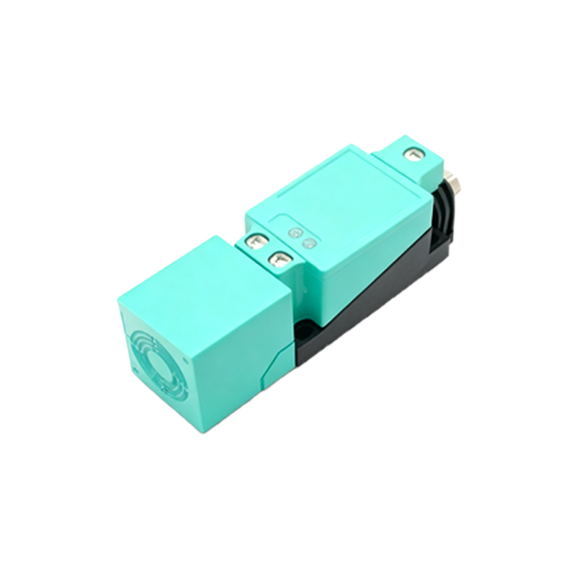
The 3-Wire DC Proximity Sensor (Most Common)
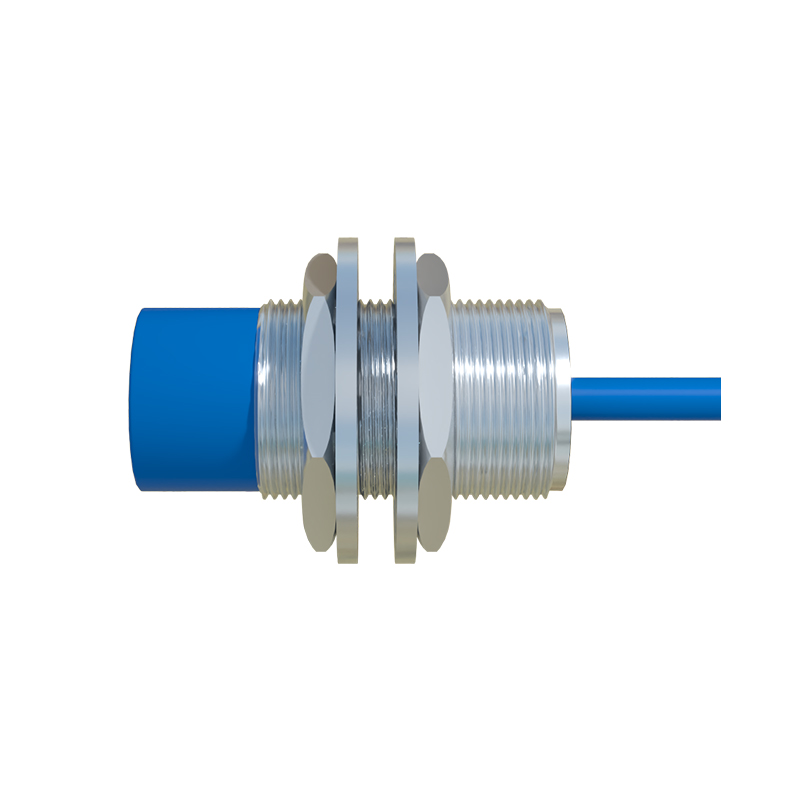
This is the standard configuration, offering clear separation of power supply and load. The wires are typically color-coded: Brown for positive supply (+V), Blue for negative supply (0V or Common), and Black for the output signal.
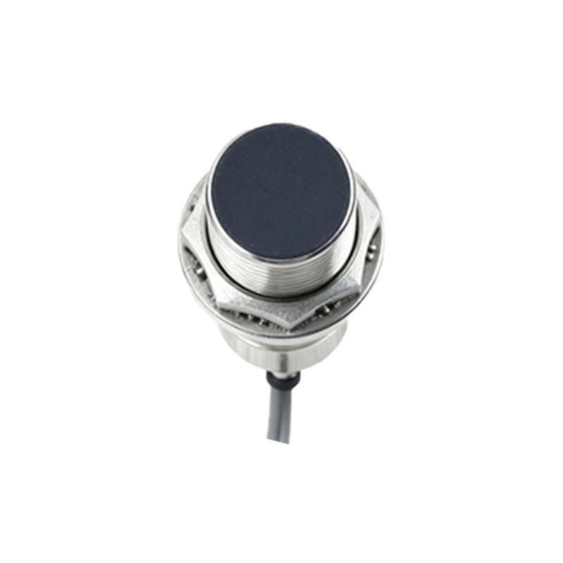
PNP (Sourcing) Wiring: In a PNP sensor, the Brown wire connects to +V (e.g., +24V DC), and the Blue wire connects to 0V. The Black output wire acts as a source of positive voltage. When the sensor detects a target, it switches the Black wire to +V, sourcing current to the load. The load (e.g., a PLC input, relay coil) is connected between the Black wire and 0V. Current flows from the sensor, through the load, to ground.
NPN (Sinking) Wiring: Here, the Brown and Blue connections remain the same (+V and 0V). The Black output wire, however, acts as a sink to ground. When activated, the sensor switches the Black wire to 0V. The load must be connected between +V and the Black wire. Current now flows from +V, through the load, and into the sensor's Black wire to ground.
Crucial Diagram Interpretation:
A typical wiring diagram will show the sensor symbol with three terminals. For a PNP sensor, the load is drawn between the output (Black) and the negative rail (Blue). For an NPN sensor, the load is drawn between the positive rail (Brown) and the output (Black). Mismatching a PNP sensor with an NPN input circuit, or vice versa, will result in a non-functional system. Many modern PLCs and controllers can accept either type, but their input card configuration must match the sensor's output.
The 2-Wire AC/DC Proximity Sensor
These sensors simplify wiring by combining the power supply loop and the load switching in two wires. They are connected in series with the load and the power source, much like a traditional switch. One wire goes to the positive or live side of the supply, the other wire goes to one side of the load, and the load's other side completes the circuit to the negative or neutral. A critical consideration is the leakage current (a few mA). Even when "off," a small current flows. The load must have a low enough impedance to prevent this leakage current from inadvertently activating the device (e.g., causing a PLC input to stay ON). A bleeder resistor placed in parallel with the load is often required to shunt this leakage current.
Wiring Best Practices and Troubleshooting:
1. Power Supply: Always use a regulated, stable DC power supply for DC sensors. Ripple and noise can cause erratic operation.
2. Shielding & Separation: Keep sensor cables away from high-voltage power lines, motor drives (VFDs), and welding equipment to prevent electromagnetic interference (EMI). Use shielded cables for long runs, grounding the shield at the controller end only.
3. Short-Circuit Protection: While many sensors have built-in protection, incorporating a fast-blow fuse (rated just above the sensor's operating current) in the supply line is a prudent safety measure.
4. Load Considerations: Do not exceed the sensor's maximum switching current. For inductive loads like relay coils, use a flyback diode (for DC) or a snubber circuit (for AC) across the load to suppress voltage spikes that can damage