In the realm of industrial automation and control systems, proximity switches are indispensable components for detecting the presence or absence of objects without physical contact. Among their fundamental operational characteristics, the concepts of "Normally Open" (NO) and "Normally Closed" (NC) are paramount. These terms define the default electrical state of the switch contacts when the sensor is in its non-activated or "normal" condition—specifically, when no target is within its sensing range. A clear grasp of this distinction is critical for proper circuit design, safety integration, and troubleshooting.
A Normally Open (NO) proximity switch has contacts that are open, meaning no electrical continuity exists between its output terminals, when no target is detected. When a target enters the sensor's effective sensing field, the switch activates, closing the contacts and allowing current to flow. This type is often described as "making" a circuit upon detection. Conversely, a Normally Closed (NC) proximity switch has contacts that are closed, providing a continuous electrical path in its resting state. When a target is detected, the switch activates and opens the contacts, breaking the circuit. This is referred to as "breaking" a circuit upon detection.
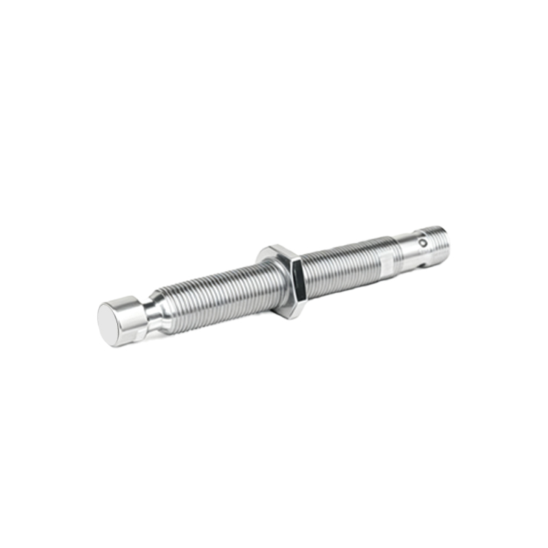
The selection between NO and NC configurations is not arbitrary; it is driven by specific application requirements, primarily focusing on safety and control logic. A fundamental principle in safety circuit design is "fail-safe" operation. Often, NC contacts are preferred for critical safety functions, such as emergency stop circuits or guard door monitoring. The rationale is that a fault condition—like a wire break, loss of sensor power, or physical damage to the sensor—will cause the NC circuit to open, mimicking the activation state and bringing the machine to a safe stop. This is inherently safer than an NO configuration, where such a fault might go undetected as an "open" circuit is its normal, non-activated state. For standard process control, the choice depends on the desired logic. An NO sensor might be used to initiate an action (e.g., start a conveyor when a part is present), while an NC sensor might be used to halt an action when an object is detected (e.g., stop filling a tank when a high level is reached).
Modern programmable logic controllers (PLCs) and control systems can typically accommodate both signal types through software logic. However, the physical wiring differs. A standard 3-wire DC proximity sensor (with Brown/+V, Blue/0V, and Black output wires) can often be specified as either NO or NC, or sometimes feature a switchable output. In a standard sinking (NPN) or sourcing (PNP) configuration, the Black wire provides the switched output signal. For an NO sensor, the signal voltage appears on the Black wire only when activated. For an NC sensor, the signal voltage is present at rest and disappears when activated. It is crucial to consult the sensor's datasheet for the exact wiring diagram and terminal designations.
Understanding the electrical schematics is essential. In ladder logic diagrams, an NO contact is represented by a symbol that looks like a break in a line, while an NC contact is shown as a line with a diagonal slash through it. When programming, the logic instruction for an NO contact is typically a standard examine-if-on (XIO) or load (LD) instruction, expecting a "1" or "ON" state when the sensor is active. For an NC contact physically wired, the programmer often uses an examine-if-off (XIC) or load-not (LDN) instruction to achieve the correct logical outcome in the program, translating the physical open circuit into a logical "true" condition for the control sequence.
Common applications illustrate the practical use. An NO inductive proximity switch is frequently used for part counting on a conveyor; each detected part closes the circuit, sending a pulse to the counter. An NC capacitive proximity switch might monitor the level of a non-metallic liquid in a tank; the circuit remains closed until the liquid reaches the sensor, opening the circuit and signaling the control system to stop the inflow pump. In robotic work cells, NC safety light curtains are standard; the beam path being closed (unbroken) keeps the circuit closed, allowing operation. Any interruption (a person entering) opens the circuit, triggering an immediate stop.
In conclusion, the choice between normally open and normally closed proximity switches is a foundational decision in control system design. It hinges on the critical interplay between desired machine logic and paramount safety requirements. Engineers must evaluate whether the application demands an action to occur upon detection (often NO) or a cessation of action upon detection (often NC), while always prioritizing fail-safe design principles for personnel and equipment protection. Proper specification, wiring, and programming of these two contact types ensure reliable, efficient, and safe operation of automated industrial machinery.