Time-of-Flight (TOF) laser sensors have become indispensable tools in modern industrial automation, offering precise, contactless distance measurement and object detection. Their configuration, however, is critical to unlocking their full potential and ensuring reliable operation in diverse and often challenging environments. This guide outlines key configuration parameters and best practices for engineers integrating TOF sensors into their systems.
The fundamental principle of a TOF sensor is straightforward: it emits a modulated laser pulse and measures the time taken for the reflection to return. The distance is calculated based on the speed of light. Yet, translating this simple principle into stable, accurate readings requires careful attention to several setup parameters.
1. Setting the Measurement Mode and Range:
Most industrial TOF sensors offer multiple operating modes. The primary choice is often between *single-shot* and *continuous* measurement. Single-shot mode is ideal for triggered applications, such as checking the height of a product on a conveyor at a specific point, conserving power and reducing processing load. Continuous mode provides a constant stream of distance data, necessary for monitoring fill levels in tanks or tracking object position in real-time. Always select the minimum effective measurement range for your application. A shorter configured range can improve the sensor's response time and signal-to-noise ratio by limiting the time window in which it listens for a return signal.
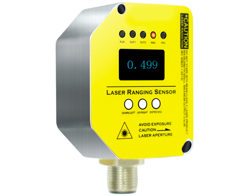
2. Configuring Output and Logic:
The output type must match your control system. Common options include analog (4-20 mA or 0-10 V), discrete digital (PNP/NPN), and serial communications (RS-485, IO-Link, Ethernet/IP). For analog output, you must map the measured distance range to the full output signal span. For instance, a 0-1000mm measurement range could be linearly scaled to 4-20 mA. Digital outputs are typically used for window comparators: you set a *threshold* distance and a *hysteresis* band. The output switches state when an object is detected within (or outside) the set window. Hysteresis is crucial to prevent output chatter when an object lingers near the threshold due to vibration or minor measurement variance.
3. Optimizing for the Target Surface:
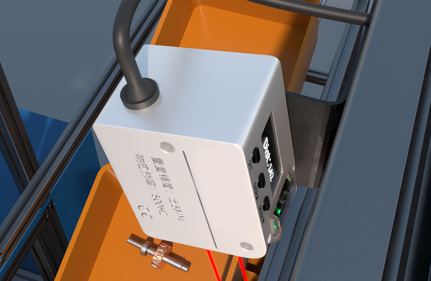
The target's surface properties dramatically affect performance. A TOF sensor works best with diffuse, matte surfaces. For highly reflective or shiny targets, the laser beam can specularly reflect away from the sensor, causing a dropout. Conversely, dark, absorbent materials like black rubber or velvet can severely attenuate the signal. Many advanced sensors feature a *response time* or *filtering* adjustment. Slowing the response time (applying a software filter) can stabilize the reading on poor surfaces but at the cost of detection speed. Some models also offer a "teaching" function to calibrate the sensor to a specific target material under actual conditions.
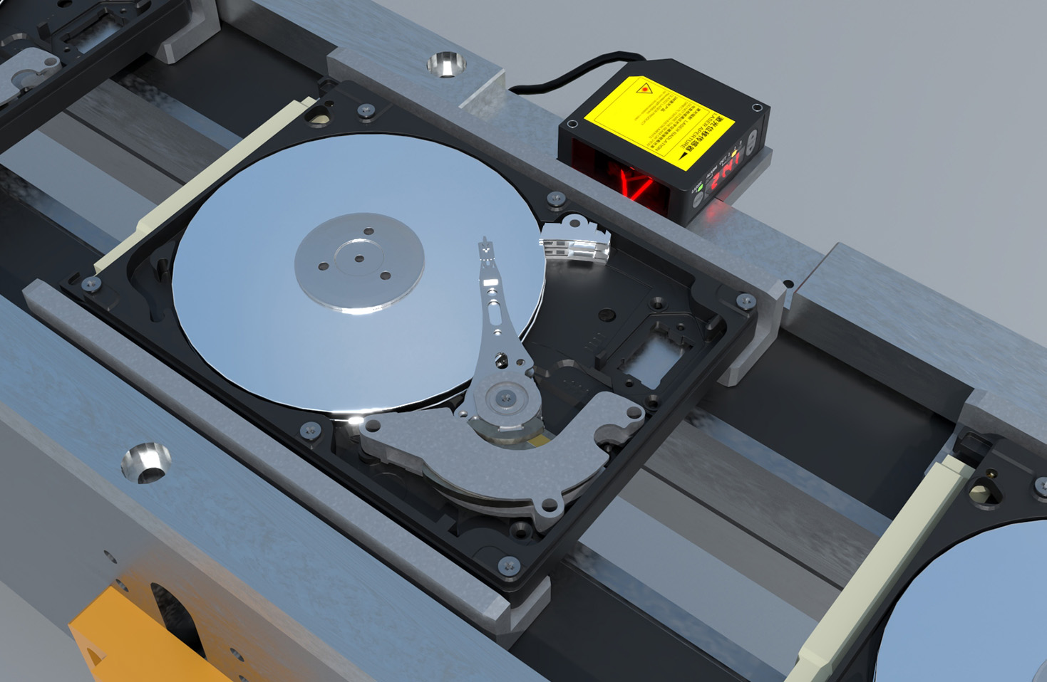
4. Managing Environmental Interference:
Industrial settings are rife with potential interference. *Ambient light* from high-bay LEDs, sunlight, or other machinery can flood the sensor's receiver. Always ensure the sensor has adequate ambient light immunity specifications for your environment. Using sensors with narrow-band optical filters matched to the laser wavelength is highly recommended. *Cross-talk* occurs when multiple TOF sensors are aimed at each other or when their beams intersect. To mitigate this, utilize models with programmable emission delays or modulation codes that allow them to ignore signals from other units. Physical mounting angle adjustments can also help.
5. Advanced Parameter Tuning:
For precision applications, delve into advanced menus. *Averaging* combines multiple measurements to produce a more stable output but increases latency. *Peak Detection* settings can help in applications with transparent objects (like glass or plastic films) by identifying the strongest return signal among possible reflections from the front and back surfaces. *Background suppression* functions allow the sensor to ignore objects beyond a certain distance, focusing only on the foreground area of interest, which is vital in cluttered spaces.
Installation and Commissioning Checklist:
* Mounting: Ensure a rigid, vibration-free mount. Even slight movement can cause measurement drift.
* Alignment: Precisely align the sensor perpendicular to the target surface for optimal signal return. Use the built-in alignment aid (often an LED) if available.
* Field Testing: Never finalize configuration in a lab. Test under real operating conditions—with the actual target materials, at the required speeds, and with all ambient machinery running.
* Diagnostics: Utilize diagnostic features like signal strength indicators (often shown as a bar graph or numerical value in configuration software) to quantitatively assess setup quality. A low signal strength reading indicates a need for re-alignment, surface adjustment, or sensor model change.
Proper configuration of a TOF laser sensor is not a one-time event but an iterative process of measurement, adjustment, and validation. By systematically addressing measurement mode, output logic, target characteristics, and environmental factors, engineers can deploy these powerful sensors to achieve high levels of automation accuracy, repeatability, and reliability. Always consult the specific manufacturer's manual for detailed instructions on accessing and setting parameters for your sensor model.