In industrial automation and control systems, proximity sensors play a critical role in detecting the presence or absence of objects without physical contact. Among the various types, normally closed (NC) proximity sensors are widely used for safety and specific control functions. Distinguishing a normally closed sensor from its normally open (NO) counterpart is essential for proper system design, wiring, and troubleshooting. This article provides a comprehensive guide on identifying and understanding normally closed proximity sensors, focusing on practical methods and industry standards.
First, it is important to grasp the fundamental concept of "normally closed." In a proximity sensor, the term refers to the default electrical state of the output circuit when no target object is within the sensing range. For an NC sensor, the output circuit is closed (conducting) in this idle state, allowing current to flow. When a target object enters the sensing field, the circuit opens (stops conducting). This behavior contrasts with normally open sensors, where the output circuit is open when idle and closes upon detection. The NC configuration is often preferred in safety-critical applications, such as emergency stop circuits or guard door monitoring, because a broken wire or power loss typically causes the circuit to open, triggering a safe shutdown.
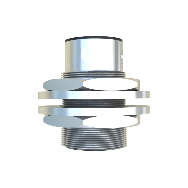
To distinguish a normally closed proximity sensor, start by examining the sensor's labeling and documentation. Manufacturers typically indicate the output type on the sensor body or datasheet using standard symbols or abbreviations. Look for markings like "NC," "N.C.," or "Normally Closed." Some sensors may use electrical symbols: a closed switch icon represents NC, while an open switch icon denotes NO. Additionally, check the part number or model code, as many manufacturers embed output configuration information in these identifiers. For example, a suffix like "-NC" or a specific digit in the model number might indicate the normally closed variant. Always refer to the technical datasheet for confirmation, as it provides detailed specifications including output type, wiring diagrams, and electrical characteristics.

Electrical testing is a reliable hands-on method to identify an NC sensor. Using a multimeter set to resistance or continuity mode, measure the output terminals of the sensor when it is powered off and disconnected from the control system. In the absence of a target object (idle state), an NC sensor should show low resistance or continuity, indicating a closed circuit. When a target object is brought within the sensing range, the circuit should open, showing high resistance or no continuity. For a more accurate test, power the sensor according to its voltage specifications (e.g., 10-30 V DC) and use the multimeter in voltage mode. With no target present, the output voltage should match the supply voltage (if sourcing type) or be near zero (if sinking type), depending on the sensor's design. Upon detection, the voltage should change accordingly. This practical test helps verify the sensor's behavior and ensures it aligns with NC principles.
Wiring and connection diagrams are another key resource. Normally closed sensors are often integrated into control circuits with specific wiring requirements. In a typical two-wire AC or DC sensor, the NC output is connected in series with the load. For three-wire sensors, which are common in DC applications, the output wire (usually black or blue) is configured as NC. The wiring diagram, typically found on the sensor or in the manual, will show the output contact as normally closed. In programmable logic controller (PLC) systems, the NC sensor's signal is usually represented as a "1" or high state when idle, switching to "0" or low upon detection. Understanding these diagrams aids in correct installation and prevents errors that could lead to system malfunctions.
Industry standards and applications also provide clues. Normally closed proximity sensors are frequently used in fail-safe designs, where a fault condition must default to a safe state. For instance, in machine guarding, an NC sensor monitoring a safety door will keep the circuit closed while the door is shut, allowing machine operation. If the door opens, the sensor opens the circuit, stopping the machine. This logic aligns with safety standards like ISO 13849 or IEC 62061. By considering the application context—such as whether the sensor is part of a safety interlock or a routine detection task—you can infer its likely configuration. However, always verify through documentation or testing, as assumptions based solely on application can be misleading.
In summary, distinguishing a normally closed proximity sensor involves a combination of reviewing labels and datasheets, performing electrical tests, analyzing wiring diagrams, and understanding industry practices. Mastery of these methods ensures reliable sensor selection and integration, enhancing system safety and efficiency. As technology evolves, with smart sensors offering configurable outputs, the principles remain rooted in clear identification and verification. For engineers and technicians, this knowledge is indispensable in designing and maintaining robust automation systems.