In modern industrial automation and precision measurement, the integration of laser sensors with display screens is a fundamental task for real-time monitoring and data visualization. This process, while straightforward in concept, requires careful attention to electrical compatibility, signal interfacing, and software configuration to ensure accurate and reliable operation. This guide provides a step-by-step overview for engineers and technicians on successfully connecting a laser sensor to a screen.
First, understand the core components. A typical laser sensor, such as a triangulation or time-of-flight sensor, outputs a measurement signal. This signal can be analog (e.g., 0-10V, 4-20mA) or digital (e.g., RS-232, RS-485, Ethernet/IP, PROFINET). The display screen, which could be a simple LCD monitor, an HMI (Human-Machine Interface) panel, or a PC-based SCADA system, must have an input capable of interpreting this signal.
The connection process begins with hardware interfacing. For analog sensors, check the sensor's output specifications and the screen's input specifications. A common setup involves connecting the sensor's output wires (signal+ and signal-) to the corresponding analog input terminals on the display device or an intermediary PLC (Programmable Logic Controller). Ensure proper grounding to minimize electrical noise, which is crucial for maintaining signal integrity, especially in environments with heavy machinery. For digital sensors, select the correct communication cable. An RS-232 connection typically uses a standard serial cable, while RS-485 may require a twisted-pair cable with termination resistors to prevent signal reflection. Ethernet-based sensors connect directly to a network switch, which is then linked to the screen or controlling computer.
Power supply is a critical, often overlooked aspect. Most laser sensors require a separate DC power source (commonly 12-24V DC). Verify that the power supply is stable and matches the sensor's voltage and current requirements. Never use the same power line for high-noise inductive loads like motors, as this can introduce interference into the sensor's signal.
Once the physical connections are secure, the next phase is software configuration. This step varies significantly depending on the display device. For a basic monitor receiving a video signal from a dedicated sensor interface box, configuration might be minimal. However, for HMIs or PC software, you must establish communication parameters. If using a serial protocol like RS-232, set the baud rate, data bits, parity, and stop bits on both the sensor and the HMI software to identical values. For Ethernet sensors, assign a correct IP address within the same subnet as the host computer or HMI.
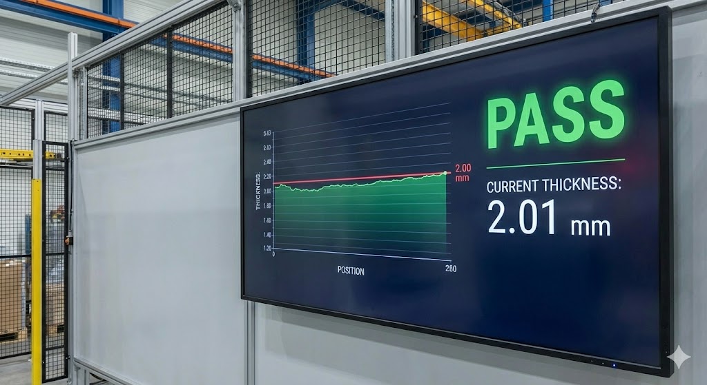
Within the HMI or SCADA software (e.g., Siemens WinCC, RockFactory Talk, Ignition), you need to create a driver or communication channel that points to the sensor's address. Then, define a tag or variable that maps to the incoming data register from the sensor. Finally, create a graphical element on the screen—such as a numeric display, bar graph, or trend chart—and link it to this tag. For analog inputs connected to a PLC, the PLC program will read the analog value, scale it to engineering units (e.g., millimeters, inches), and then pass this value to a register that the HMI can read.

Calibration and testing are imperative. After configuration, perform a functional test. Use a known reference target at a fixed distance from the laser sensor. Check if the value displayed on the screen matches the expected measurement. If there is a discrepancy, recalibrate the sensor's zero and span points if it's analog, or check the scaling formula in the software. For digital sensors, verify the data parsing logic in your HMI program.
Common troubleshooting points include checking cable integrity, verifying power levels, confirming communication settings, and ensuring no software conflicts. Electrical noise remains a prevalent issue; using shielded cables and proper grounding techniques usually mitigates this.
In summary, connecting a laser sensor to a screen is a systematic integration of hardware and software. By meticulously following electrical standards, matching communication protocols, and correctly configuring the display software, engineers can establish a robust system for real-time data visualization, enhancing process control and decision-making in industrial applications.