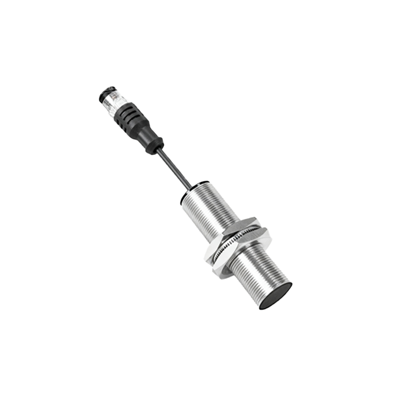
Proximity switch sensors are essential components in industrial automation, providing non-contact detection of metallic or non-metallic objects. Understanding the wiring diagram is crucial for proper installation, operation, and troubleshooting. This guide details the standard wiring configurations for common types of proximity sensors, including inductive, capacitive, and ultrasonic variants, with a focus on practical application in electrical control systems.
A typical proximity sensor features three or four wires, corresponding to power supply, output signal, and ground. For a standard 3-wire DC sensor, the wiring is as follows: Brown wire connects to the positive DC supply voltage (typically 10-30V DC). Blue wire connects to the negative DC supply (0V/common). Black wire is the output signal line, which switches to supply voltage (PNP sourcing) or to ground (NPN sinking) when a target is detected. The load (e.g., PLC input, relay coil) is connected between the black wire and the opposite supply rail, depending on the output type. For 4-wire sensors, an additional white wire often provides a complementary output or diagnostic function.
Wiring diagrams must account for sensor type (PNP vs. NPN) and load compatibility. In PNP (sourcing) configurations, the output provides positive voltage to the load; the load's other terminal is connected to ground. This is common in European and many global standards. In NPN (sinking) configurations, the output connects the load to ground; the load's other terminal is connected to positive voltage. This is frequently used in Asian and North American systems. Miswiring can lead to sensor damage, erratic operation, or control system failures. Always refer to the manufacturer's datasheet for specific voltage ratings, current limits, and wiring codes.
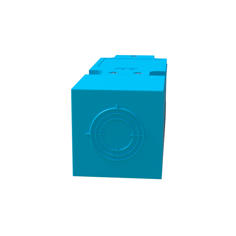
Shielding and grounding are critical for noise immunity, especially in environments with variable frequency drives or high-power equipment. Use shielded cables, connecting the shield to earth ground at the control panel end only to prevent ground loops. Ensure proper separation from high-voltage power lines. For AC-powered sensors, typically two-wire designs, wiring involves connecting one terminal to the AC line (often brown) and the other to the load (often blue), with careful attention to voltage ratings (e.g., 90-250V AC).
Installation tips include verifying sensor sensing distance and orientation, securing connections with appropriate terminals, and testing with a target before system integration. For complex systems, a detailed wiring diagram should include sensor placement, cable routing, interface with PLC modules, and protective devices like fuses or surge suppressors. Troubleshooting steps often involve checking supply voltage with a multimeter, inspecting for loose connections, and verifying output status via indicator LEDs.
Advanced sensors with IO-Link or analog outputs require additional wiring for communication or continuous signal transmission. For instance, IO-Link sensors use a standard 3-wire connection plus a dedicated communication line for parameter setting and diagnostics. Analog output sensors (e.g., 4-20mA or 0-10V) provide a variable signal proportional to distance, necessitating precise wiring to analog input modules.
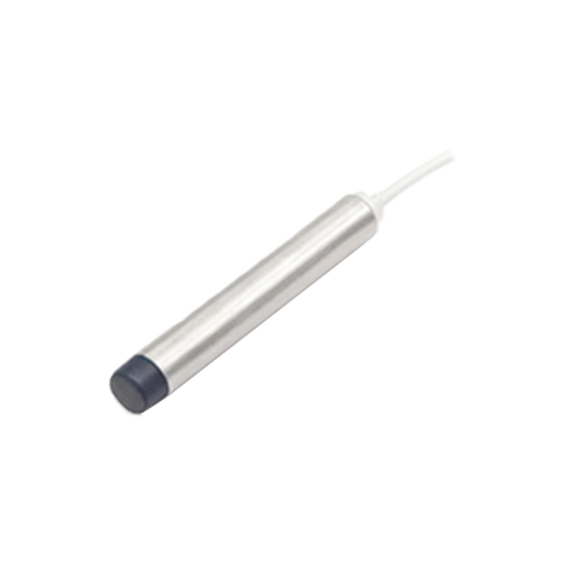
In summary, mastering proximity sensor wiring diagrams ensures reliable automation system performance. Key practices include selecting the correct sensor type for the application, adhering to wiring standards, implementing noise reduction measures, and conducting thorough testing. Always prioritize safety by disconnecting power during installation and following local electrical codes.