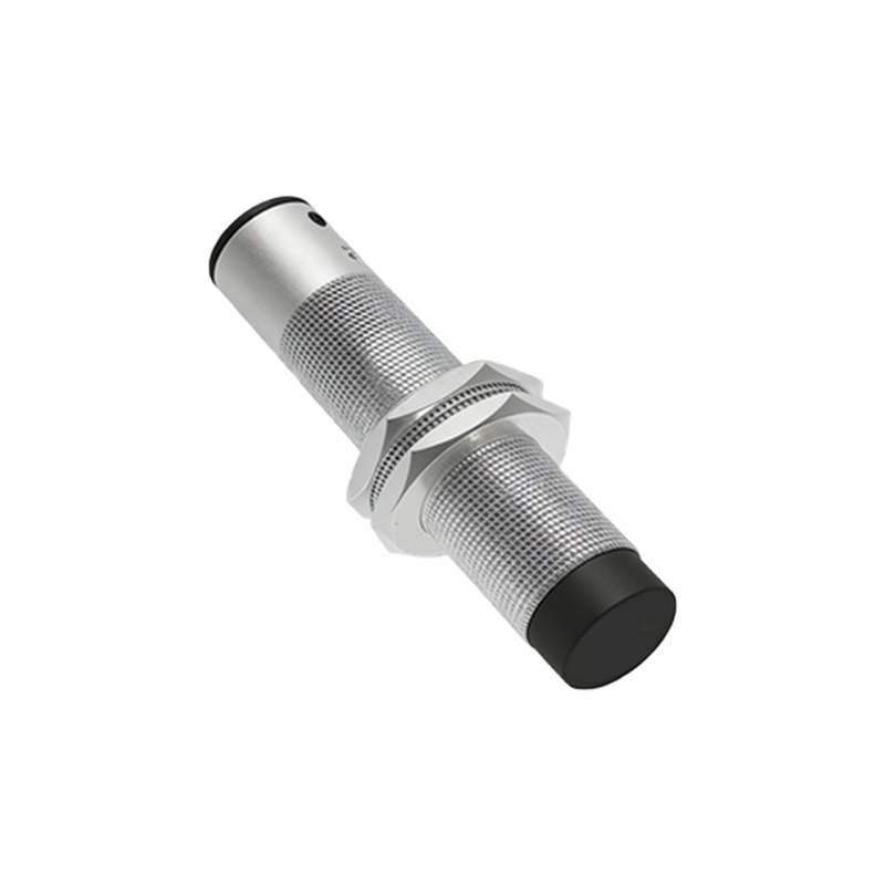
In industrial automation and electrical engineering, proximity angle sensors are critical components for precise angular position detection in rotating machinery. This article provides an in-depth technical explanation of the working principle, supported by a detailed functional diagram, tailored for electrical engineers and industry professionals.
A proximity angle sensor is a non-contact device designed to measure the angular position or rotational speed of a shaft. Unlike traditional encoders that require physical contact, these sensors operate by detecting changes in a physical field—typically magnetic or electromagnetic—generated by a target attached to the rotating element. The core principle revolves around the relationship between a moving target and a stationary sensing element.
The fundamental working principle can be broken down into several key stages, as illustrated in a standard functional diagram. First, a target, often a ferromagnetic gear tooth or a dedicated rotor with alternating poles, is mounted on the rotating shaft. The sensor itself is positioned in close proximity to this target without making physical contact. Internally, the sensor houses an oscillator circuit that generates a high-frequency electromagnetic field at its active face.
As the shaft rotates, the target's features (like teeth or protrusions) pass through this field. When a target feature approaches the sensor face, it interacts with the electromagnetic field. In inductive-type proximity sensors—the most common for metallic targets—this interaction causes eddy currents to be induced in the target material. These eddy currents draw energy from the oscillator, resulting in a measurable damping or attenuation of the oscillation amplitude. A subsequent detection circuit within the sensor monitors this amplitude change.
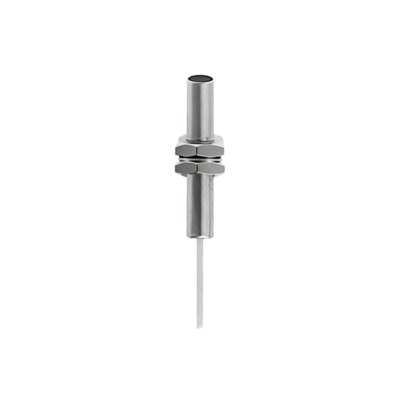
The critical stage for angle measurement is the conversion of this amplitude modulation into a digital signal. The detection circuit triggers a Schmitt trigger or a similar switching circuit when the amplitude drops below a defined threshold. This action produces a clean, digital output pulse—a high signal for the presence of a target feature and a low signal for its absence. For a rotating gear, this generates a series of pulses directly corresponding to the passing of each tooth.
The angle measurement is derived from this pulse train. The sensor's output is connected to a controller, such as a PLC or a dedicated motion controller. The controller counts the number of pulses over a specific time interval. Knowing the number of target features (e.g., 60 teeth on a gear) allows the system to calculate the angular displacement precisely. For instance, one complete revolution generating 60 pulses means each pulse represents 6 degrees of rotation. By measuring the time between consecutive pulses, the controller can also compute the instantaneous angular velocity.
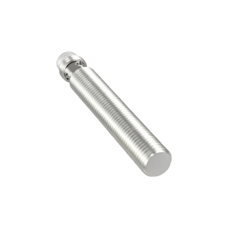
The accompanying principle diagram visually maps this process: It shows the rotating shaft with the target gear, the sensor's fixed position, the oscillating electromagnetic field lines, and the resulting waveform transformation from a sinusoidal field disturbance to a squared digital output pulse. The diagram typically includes blocks for the oscillator, demodulator/detector, output driver, and the connection to the external counter/timer input of a controller.
Key design considerations include the sensor's sensing distance, target material and geometry, operating frequency (response time), and environmental robustness against factors like temperature, vibration, and electromagnetic interference (EMI). Modern Hall-effect-based proximity sensors operate on a similar non-contact principle but detect changes in magnetic field strength from a magnetic target, offering advantages in dirty environments.
Understanding this working principle diagram is essential for proper sensor selection, installation, and troubleshooting in applications ranging from motor speed feedback and conveyor belt synchronization to robotic arm positioning and CNC machine tool indexing, ensuring reliable and accurate angular data for closed-loop control systems.