In industrial automation and control systems, proximity sensors play a critical role in detecting the presence or absence of objects without physical contact. Among various types, 3-wire DC proximity sensors are widely adopted due to their reliability and straightforward integration. This article provides a detailed guide on the 3-wire connection method, complete with diagrams and practical considerations for engineers and technicians.
A standard 3-wire DC proximity sensor typically includes three distinct wires: brown (positive supply), blue (negative supply or common), and black (output signal). The brown wire connects to the positive terminal of the DC power source, usually ranging from 10-30 VDC, depending on the sensor model. The blue wire is linked to the negative terminal or ground of the power supply. The black wire serves as the output, which can be either sourcing (PNP) or sinking (NPN) configuration, determining how the sensor interfaces with the controller (e.g., PLC).
For a PNP (sourcing) sensor, the black wire outputs a positive voltage when an object is detected, effectively "sourcing" current to the load. In contrast, an NPN (sinking) sensor switches the negative side, "sinking" current from the load to ground upon detection. It is crucial to match the sensor type with the control system's input requirements to avoid malfunctions. The wiring diagram illustrates these connections clearly: the power supply connects to brown and blue wires, while the black wire runs to the controller input, often with a protective device like a fuse or relay in series.
When implementing the wiring, several best practices ensure optimal performance. First, always verify the sensor's specifications, including voltage ratings, output current, and switching frequency, to prevent damage. Use shielded cables in environments with high electromagnetic interference (EMI) to reduce noise and false triggers. Proper grounding of the shield and power supply is essential for stability. Additionally, maintain appropriate cable lengths—excessive length can lead to voltage drop or signal degradation. For safety, disconnect power during installation and test the sensor with a target object to confirm correct operation.
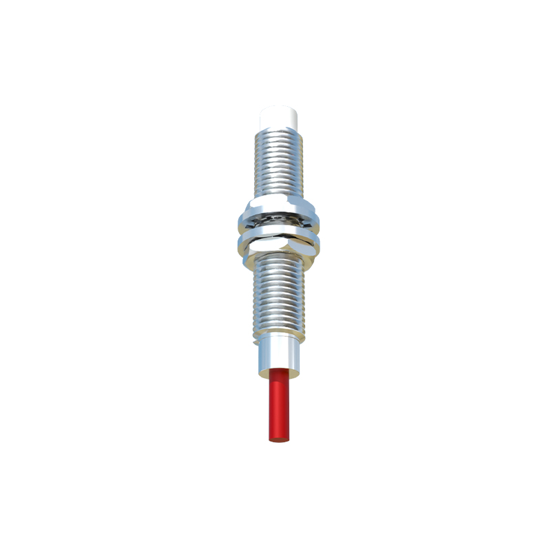
Common issues in 3-wire setups include incorrect polarity, miswired outputs, or power mismatches. If the sensor fails to activate, check the voltage at the brown and blue wires with a multimeter. For erratic behavior, inspect for loose connections or environmental factors like dirt or moisture. Regular maintenance, such as cleaning the sensor face and checking wire integrity, prolongs lifespan and ensures consistent detection.
In summary, understanding the 3-wire connection for proximity sensors is fundamental for efficient system design. By following the diagram and guidelines, engineers can achieve reliable object detection, enhancing automation processes. Always refer to the manufacturer's datasheet for model-specific details, as variations may exist in wire colors or functions. With proper installation, these sensors contribute to robust and safe industrial operations.