Proximity sensors are essential components in industrial automation, offering non-contact detection of metallic or non-metallic objects. Proper wiring is critical to ensure reliable operation, safety, and longevity. This article explores common wiring methods for proximity sensors, focusing on two-wire, three-wire, and four-wire configurations, along with practical considerations for installation.
Two-wire proximity sensors are the simplest type, consisting of only two wires for both power supply and load connection. They are directly connected in series with the load, making installation straightforward. However, they have a residual current when off, which may cause issues with low-power loads. These sensors are commonly used in applications where simplicity and cost-effectiveness are priorities, such as in basic conveyor systems or lighting controls.
Three-wire proximity sensors are the most widely used in industrial settings due to their reliability and flexibility. They feature separate wires for power supply (typically brown for positive, blue for negative) and a signal output wire (black or white). The output can be either NPN (sinking) or PNP (sourcing). NPN sensors switch the negative side of the load, while PNP sensors switch the positive side. Proper selection depends on the control system's requirements—for instance, PLC input modules often specify NPN or PNP compatibility. Shielding and grounding are crucial to prevent electrical noise interference, especially in environments with motors or frequency drives.
Four-wire proximity sensors include two output wires, allowing for both normally open (NO) and normally closed (NC) contacts. This configuration provides versatility for complex control logic, such as safety circuits or dual-signal applications. Wiring involves connecting power supply wires and selecting the appropriate output based on the desired function. These sensors are ideal for machinery requiring redundant signals or fail-safe operations.
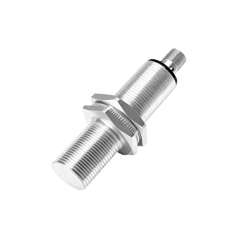
Key installation tips include: verifying voltage ratings (e.g., 10-30V DC or 90-250V AC), ensuring correct polarity for DC sensors, and using conduit or cable glands in harsh environments. For long-distance wiring, consider voltage drop and use shielded cables to minimize electromagnetic interference. Always refer to manufacturer datasheets for specific wiring diagrams and specifications.
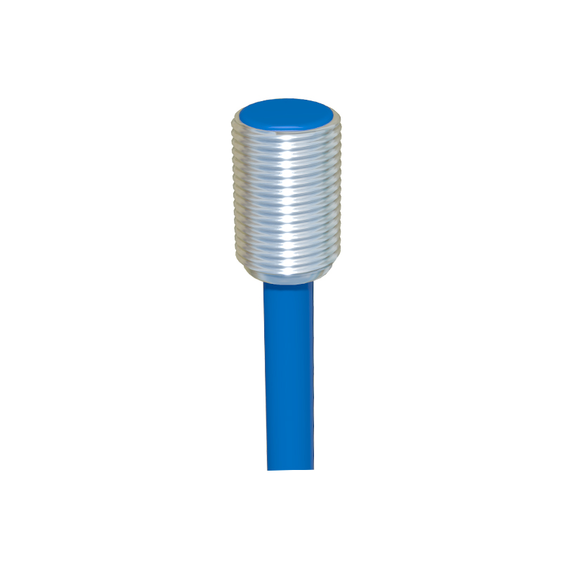
In summary, choosing the right wiring method depends on application needs, control system compatibility, and environmental factors. Two-wire sensors offer simplicity, three-wire sensors balance performance and cost, and four-wire sensors deliver advanced functionality. Proper installation and maintenance ensure optimal sensor performance, reducing downtime in automated processes.