In industrial automation and control systems, proximity sensors are fundamental components for detecting the presence or absence of objects without physical contact. Among their various configurations, the Normally Closed (NC) contact type presents a unique set of operational principles and measurement considerations that are critical for system reliability and safety. This article delves into the technical aspects of Normally Closed contact measurement in inductive and capacitive proximity sensors, providing a comprehensive guide for engineers and technicians.
A Normally Closed (NC) contact, in the context of a proximity sensor, refers to an output circuit that is closed (allowing current to flow) when the sensor is in its idle or non-actuated state. When a target object enters the sensor's detection field, the output circuit opens, interrupting the current flow. This behavior is the inverse of the more common Normally Open (NO) configuration. The choice between NO and NC is not arbitrary; it is often dictated by fail-safe design principles. In safety-critical applications, an NC configuration can be preferable because a wire break or loss of power in the sensor's loop will cause the circuit to open, signaling a fault condition—a principle known as "de-energize to trip."
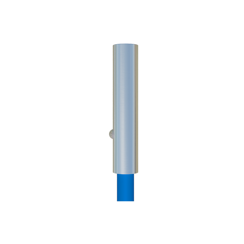
Measuring and verifying the performance of an NC contact requires a clear understanding of its electrical characteristics. The primary parameters include the leakage current in the open state, the voltage drop in the closed state, and the switching behavior (hysteresis). When the NC contact is closed (no target present), it should present a very low impedance, typically resulting in a minimal voltage drop (often less than 2V for solid-state outputs) across the sensor when carrying its rated load. Conversely, when the contact is open (target detected), the impedance should be very high, leading to a leakage current specification that is usually in the microampere range. Exceeding this leakage current can cause false signals in sensitive control inputs.
Practical measurement involves using a digital multimeter (DMM) or an oscilloscope under realistic load conditions. To measure the closed-state voltage drop, connect the sensor in series with its specified load (e.g., a relay coil or PLC input) and a power supply. With no target present, measure the voltage directly across the output terminals of the sensor. A significantly higher-than-specified drop indicates excessive internal resistance, which could lead to insufficient voltage for the load device. To measure open-state leakage, introduce a target to actuate the sensor. With the circuit open, the multimeter, set to measure current in series, will show the tiny leakage current. It is crucial to compare this reading with the sensor's datasheet specifications.
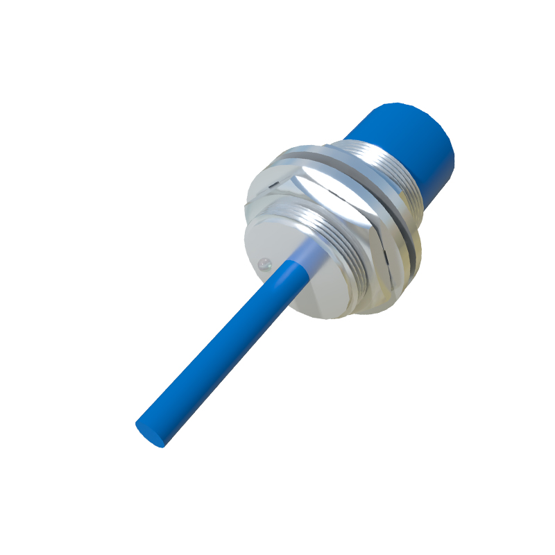
For AC-powered proximity sensors with relay outputs, the measurement focuses on contact resistance. Using a low-resistance ohmmeter or a dedicated contact resistance tester, measure the resistance across the NC terminals with the sensor de-energized and no target present. The resistance should be exceptionally low, typically in the milliohm range. High or unstable contact resistance is a primary indicator of contact wear, oxidation, or impending failure, which can cause overheating and unreliable switching.
System integration of NC sensors demands careful attention to logic. Programmable Logic Controller (PLC) input cards are typically wired to source current. When an NC sensor is connected, the PLC input will see a "TRUE" or "1" signal (due to current flow) when no target is present. The ladder logic programming must account for this inverted logic. A common best practice is to document the sensor state explicitly, using comments like "Part Present Sensor (NC)" and programming the contact instruction accordingly (often using a normally closed instruction in the ladder for an NC physical sensor to achieve the correct operational logic).
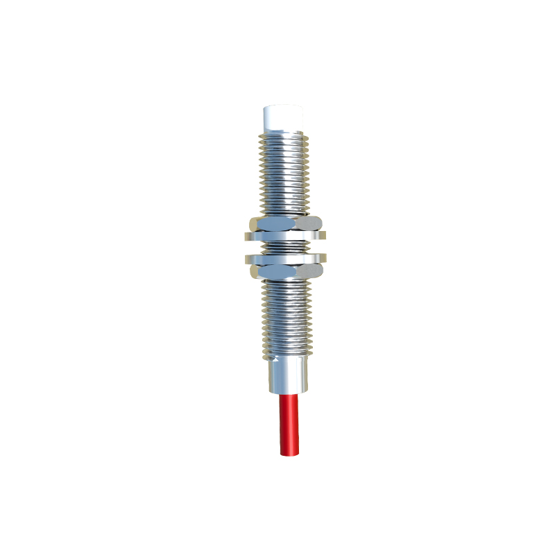
Troubleshooting NC circuits often starts with a voltage check. If a machine is faulted because a "part present" signal is missing, but the part is indeed in place, checking the voltage at the PLC input can quickly isolate the issue. If the NC sensor is open (as it should be with a target), the PLC input voltage should be near zero. If voltage is present, the sensor may have failed closed, the wiring may be faulty, or the target may be outside the sensing range. Understanding the expected state versus the measured state is the key to efficient diagnostics.
In conclusion, the proper application and measurement of Normally Closed contacts in proximity sensors are pillars of robust control system design. By prioritizing accurate measurement of voltage drop and leakage current, adhering to fail-safe wiring practices, and correctly implementing the inverted logic in software, engineers can ensure higher system availability, enhanced safety, and simplified troubleshooting. Always consult the specific manufacturer's datasheet for precise tolerances and testing procedures, as specifications can vary between different sensor technologies and brands.