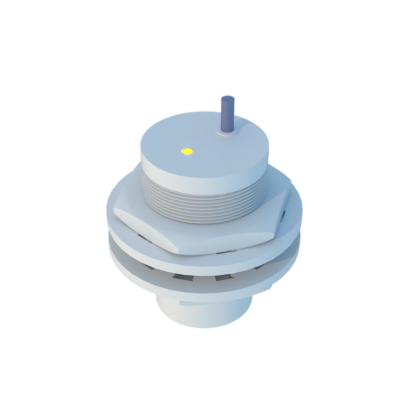
Fiber optic proximity sensors are essential components in modern industrial automation, offering high precision, immunity to electromagnetic interference, and versatility in harsh environments. Proper setup is critical to ensure reliable operation and longevity. This guide provides a step-by-step approach to configuring these sensors effectively.
First, understand the sensor type. Fiber optic sensors come in two main variants: through-beam and diffuse reflective. Through-beam sensors consist of separate transmitter and receiver units, ideal for long-range detection or transparent objects. Diffuse reflective sensors use a single unit that emits light and detects reflections, suitable for shorter distances and varied surfaces. Select the type based on your application requirements, such as detection range, object material, and environmental conditions.
Begin installation by mounting the sensor securely. Ensure the fiber optic cable is positioned correctly, avoiding sharp bends or tension that could damage internal fibers. The bending radius should exceed the manufacturer’s specification, typically 10 times the cable diameter. Align the sensor head precisely with the target area. For through-beam types, align the transmitter and receiver axes to maximize signal strength. Use mounting brackets or adjustable holders to fine-tune positioning, especially in vibrating or mobile setups.
Next, connect the sensor to a compatible amplifier or controller. Most fiber optic sensors require an external amplifier to process signals. Check the wiring diagram: typically, brown wire connects to positive voltage (10-30V DC), blue to negative or ground, and black to output. Ensure power supply matches the sensor’s voltage rating. For digital amplifiers, use the teach-in function to set sensitivity. Place the target object within the detection zone and press the teach button to calibrate the threshold. Adjust sensitivity gradually to avoid false triggers from background reflections or dust.
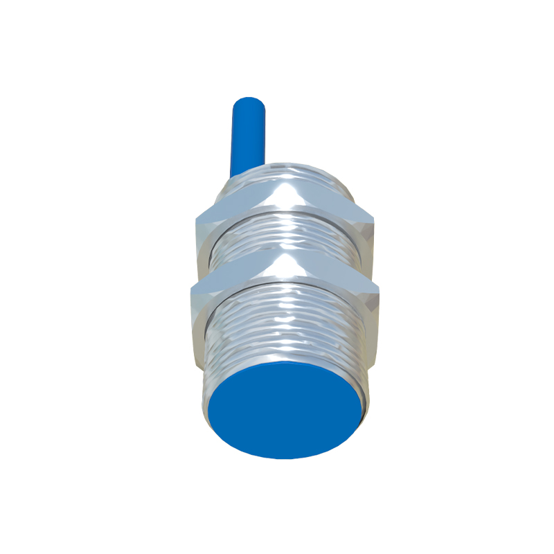
Calibration is crucial for accuracy. For diffuse sensors, account for object color and reflectivity. Dark surfaces absorb light, reducing signal strength—increase sensitivity accordingly. Transparent objects may require through-beam sensors or specialized polarized lenses. Test with actual objects under operating conditions. Use the amplifier’s LED indicators: green for power, yellow for signal stability. If the signal fluctuates, reposition the sensor or adjust sensitivity. For analog sensors, set the response time to filter noise without delaying detection.
Environmental factors must be considered. Fiber optic sensors excel in extreme temperatures, corrosive areas, or high-noise settings, but the cable jacket material should match the environment (e.g., PVC for chemicals, stainless steel for high heat). Keep lenses clean from oil, debris, or condensation, which can scatter light. Regularly inspect cables for wear and tear.
Finally, validate the setup through operational tests. Simulate production cycles to ensure consistent detection. Monitor output signals via oscilloscope or PLC diagnostics. Document settings for future maintenance. Common issues include intermittent signals due to misalignment or insufficient sensitivity—recalibrate as needed.
By following these steps, engineers can optimize fiber optic proximity sensors for precise, reliable performance in diverse industrial applications, enhancing automation efficiency and reducing downtime.