Proximity sensors are fundamental components in modern industrial automation, serving as the eyes of a control system by detecting the presence or absence of objects without physical contact. Their correct installation and wiring are paramount for reliable operation, safety, and system integrity. This guide delves into the core principles and practical details of proximity sensor wiring diagrams, catering to the needs of electrical engineers and technicians.
Understanding Sensor Types and Outputs
Before examining wiring, one must identify the sensor type and its output configuration. The two primary categories are Inductive (detecting metallic objects) and Capacitive (detecting both metallic and non-metallic objects). More critically, the output type dictates the wiring scheme. The three main output configurations are:
1. NPN (Sinking): The output acts as a switch to ground (0V). The load is connected between the positive supply voltage and the sensor's output wire. When activated, the sensor connects the load to ground, completing the circuit.
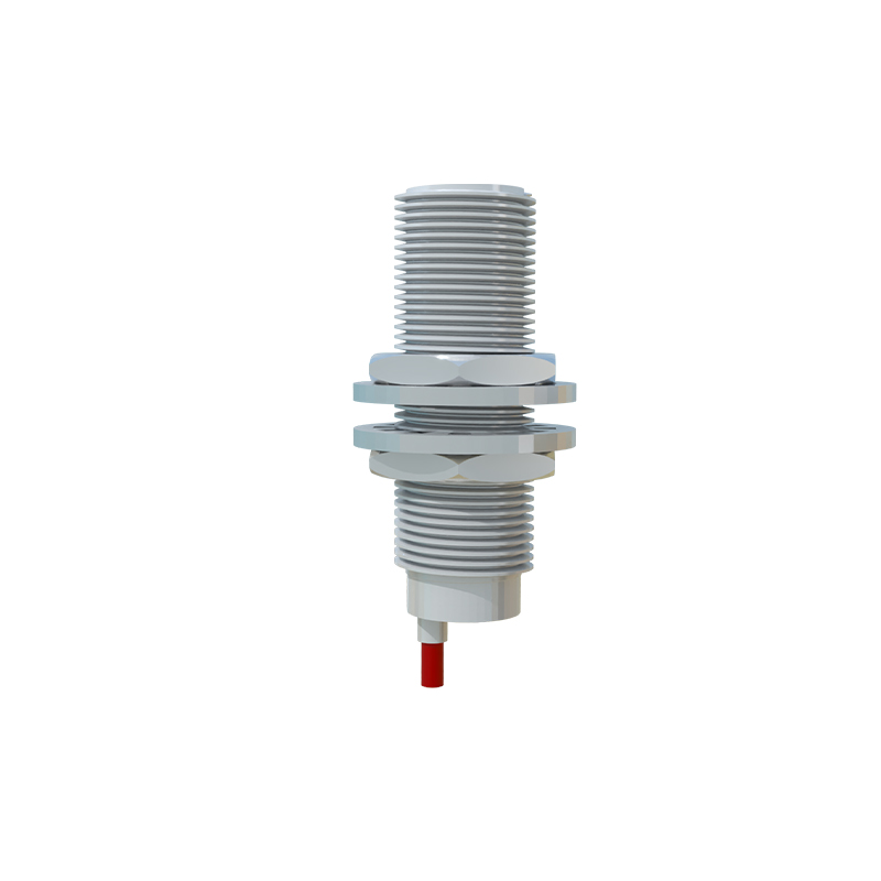
2. PNP (Sourcing): The output acts as a switch to the positive supply voltage. The load is connected between the sensor's output wire and ground. When activated, the sensor supplies positive voltage to the load.
3. NAMUR: An intrinsically safe two-wire design used in hazardous areas, requiring a separate switching amplifier interface.
Additionally, sensors are classified as Normally Open (NO) or Normally Closed (NC), defining the output state when no target is present.
Standard Wiring Color Codes and Terminals
While manufacturers' codes can vary, IEC standards provide a common framework for DC sensors:
Brown Wire: Connect to the positive DC supply voltage (typically +10 to +30 VDC).
Blue Wire: Connect to the DC common or 0V (ground).
Black Wire: The switched output signal wire.
White Wire: Often used for a second output or function (e.g., complementary output, timing function). Always consult the datasheet.
A 3-wire sensor typically uses Brown (+V), Blue (0V), and Black (Output). A 4-wire device may have two outputs (e.g., Black for NO, White for NC).
Detailed Wiring Diagrams and Analysis
1. 3-Wire DC PNP Sensor (Sourcing)
This is one of the most common configurations. The wiring is as follows:
Connect the Brown wire to the positive terminal of your DC power supply (e.g., +24VDC).
Connect the Blue wire to the negative terminal (0V) of the power supply and to one side of the load (e.g., PLC input, relay coil).
Connect the Black (output) wire to the other side of the load.
Operation: When a target is detected, the PNP sensor switches its internal circuit, sourcing positive voltage from the Brown wire to the Black output wire. This supplies power to the load, completing the circuit to ground via the Blue wire.
2. 3-Wire DC NPN Sensor (Sinking)
The complementary setup to PNP:
Connect the Brown wire to the positive terminal of your DC power supply (+V).
Connect the Blue wire to the negative terminal (0V) of the power supply.
Connect one side of the load to the positive supply (+V).
Connect the other side of the load to the Black (output) wire of the sensor.
Operation: When activated, the NPN sensor connects the Black output wire internally to the Blue wire (0V). This sinks the current from the load to ground, completing the circuit.
Critical Considerations for Reliable Wiring
Power Supply: Ensure the supply voltage matches the sensor's rated voltage. Use a regulated and filtered power supply to avoid voltage spikes and noise.
Load Compatibility: Verify that the sensor's maximum output current rating is not exceeded by the load. For heavy loads (like large contactor coils), use an intermediate relay.
Shielding and Cable Routing: In electrically noisy environments (e.g., near VFDs, motors), use shielded cables. Connect the cable shield to a functional earth ground at the controller end only. Route sensor cables separately from power cables.
Protection Circuits: Incorporate protective devices such as:
Fuse: A small-value fuse (e.g., 100mA) in series with the Brown wire protects against short circuits.
Flyback/Suppression Diode: For inductive loads (relays, solenoids), place a diode in reverse bias across the load to suppress voltage transients that can damage the sensor's