In the dynamic field of industrial automation and electrical engineering, proximity sensors are indispensable components, providing non-contact detection of metallic and non-metallic objects. Their reliability is paramount for system integrity, making precise detection and diagnostics a critical task. This necessitates the use of specialized tools designed specifically for proximity sensor applications. Unlike general-purpose multimeters, these tools offer targeted functionality that enhances accuracy, efficiency, and safety in commissioning, maintenance, and troubleshooting procedures.
The cornerstone of proximity sensor toolkits is the dedicated sensor tester or simulator. These handheld devices are engineered to interact directly with the common output types: NPN, PNP, and Namur. A high-quality tester performs multiple functions. Primarily, it can simulate a target's presence or absence, sending a signal to the sensor to trigger its switching response. This allows an engineer to verify the sensor's basic operation independently of the actual machinery, a crucial step during installation or when diagnosing a suspected faulty sensor. Conversely, the tool can also act as a monitor, detecting the output signal from a functioning sensor when a real target is introduced. Advanced models feature digital displays showing output status, voltage levels, current sink/source values, and even switching frequency, providing a comprehensive snapshot of sensor health.
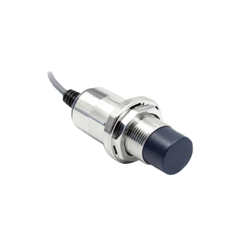
For analog or measuring proximity sensors, which output a current or voltage signal proportional to distance, a precise current loop calibrator or a high-impedance digital multimeter (DMM) becomes essential. These tools measure the 4-20 mA or 0-10 VDC output with minimal circuit loading, ensuring the measured value accurately reflects the sensor's performance relative to its set sensing range. Calibrators can also simulate these analog signals to test the responsiveness of the connected controller (PLC) or indicator.
Another critical category is the target simulator or feeler gauge set. While a tester checks the electrical response, verifying the actual sensing distance is equally important. Manufacturers specify a nominal sensing distance (Sn), but real-world factors like target material, size, and temperature can affect it. Non-magnetic feeler gauges of precise thicknesses allow technicians to measure the exact point of switch activation for inductive sensors. For capacitive sensors, specialized dielectric test pieces are used. This practice ensures the sensor is positioned correctly and will function reliably with the intended target material.
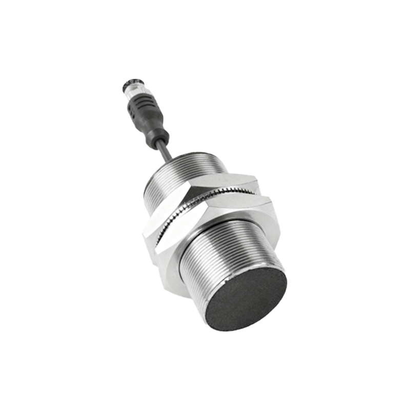
Oscilloscopes, particularly portable ones, are invaluable for diagnosing complex issues like signal instability, bounce, or response time delays. By observing the sensor's output waveform, engineers can identify noise interference, slow switching caused by excessive load capacitance, or problems with the power supply ripple. This level of analysis is often the key to solving intermittent faults that simpler testers cannot pinpoint.
When dealing with two-wire AC or DC sensors, a clamp meter capable of measuring low-level AC/DC current is highly recommended. It allows for safe, non-intrusive measurement of the sensor's quiescent and active current without breaking the circuit, facilitating quick checks under actual operating conditions.
The selection of the right tool hinges on the sensor technology (inductive, capacitive, ultrasonic, photoelectric), output type, and application environment. For instance, an intrinsically safe (IS) certified tester is mandatory for use in hazardous areas. Furthermore, tools with robust housing, clear IP ratings for dust and moisture resistance, and reliable battery life are non-negotiable for harsh industrial settings.
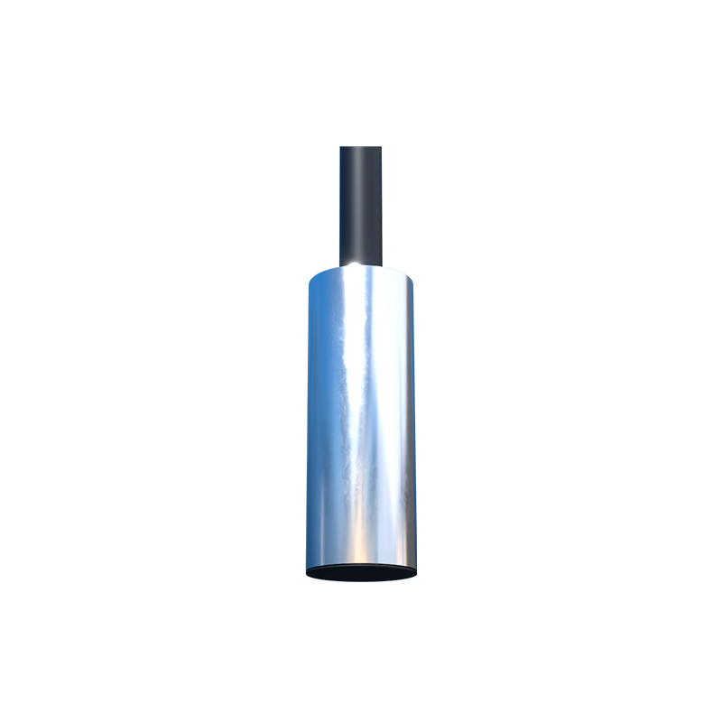
In practice, a systematic approach using these tools streamlines workflow. A typical diagnostic sequence might involve: first, using a simulator to isolate the sensor from the machine and check its basic electronic function; second, employing feeler gauges to verify its mechanical sensing distance; third, monitoring its output with a DMM or oscilloscope while in-circuit to observe real operation; and finally, using a clamp meter to assess power consumption. This methodical process quickly identifies whether the fault lies with the sensor itself, its power supply, the load (like a PLC input module), or external interference.
Investing in a comprehensive set of specialized detection tools is not merely an expense but a strategic decision that reduces machine downtime, prevents misdiagnosis, and extends the lifecycle of sensor systems. For the professional electrical engineer, mastery of these tools is as fundamental as understanding the sensors they are designed to test, ensuring precision and reliability in every automated process.