Laser sensors have become indispensable components in modern industrial automation, offering unparalleled precision, speed, and reliability for tasks ranging from object detection and positioning to measurement and quality control. Their integration with Programmable Logic Controllers (PLCs) forms the backbone of countless automated systems. Effective PLC programming is crucial to harness the full potential of these sophisticated devices. This article delves into the core principles and practical methodologies for programming PLCs to interface with laser sensors.
The foundation of any successful integration lies in understanding the sensor's output signal. Most industrial laser sensors provide discrete (digital) or analog outputs, and increasingly, IO-Link or other fieldbus communication protocols. For a simple presence detection sensor with a digital PNP or NPN output, the PLC programming is straightforward. The sensor's output channel is mapped to a PLC input (e.g., I0.0). A basic ladder logic rung would use this input contact to control an output coil or trigger internal logic. For instance, when the sensor detects an object (I0.0 = TRUE), it could set a flag (M0.0), start a timer (T1), or activate a solenoid valve (Q0.0). Debouncing logic using timers is often essential to filter out signal noise or brief interruptions.
Analog laser sensors, used for precise distance or measurement, present a more complex scenario. These sensors output a continuous current (4-20 mA) or voltage (0-10 V) signal proportional to the measured value. The PLC must read this analog value via an analog input module. The raw input value, typically a 12-bit or 16-bit integer (e.g., 0 to 27648), must be scaled within the PLC program to represent the actual engineering units, such as millimeters or inches. This is achieved using scaling function blocks (like SCALE in Siemens TIA Portal or CPT in Allen-Bradley Studio 5000) that apply linear transformation. Post-scaling, the program can implement comparison instructions to create digital thresholds for sorting, grading, or triggering corrective actions. For example, if the measured height from a laser distance sensor falls outside a defined tolerance band, the PLC can activate a reject mechanism.
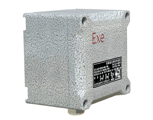
Advanced laser sensors with IO-Link or fieldbus connectivity (PROFINET, EtherNet/IP) offer significant advantages. They transmit not just the measured value but also rich parameter data and diagnostic information. Programming shifts from simple I/O mapping to device configuration and data handling within the PLC. The engineer uses the PLC programming software's hardware configuration tool to integrate the GSDML or EDS file of the sensor, establishing a seamless data exchange. Parameters like sensing mode, response time, and output logic can be set remotely from the PLC, enabling flexible changeovers. The measured values are then available in pre-defined data blocks or tags, simplifying the logic. Diagnostic bits can be monitored to predict maintenance needs, such as lens contamination or temperature warnings, enhancing overall system reliability.
Structured programming techniques are vital for maintainability. Creating dedicated function blocks (FBs) or user-defined routines for each laser sensor or a group of similar sensors is a best practice. This FB encapsulates all the logic: input scaling, limit checking, alarm generation, and diagnostic handling. It accepts the raw input or device data block as a parameter and outputs processed values and status bits. This modular approach makes the program easier to debug, modify, and reuse across multiple machines or production lines.
Error handling and diagnostics must be integral to the program. Beyond process logic, routines should monitor for sensor failures—such as a broken beam, short circuit, or communication loss (for networked sensors). This is often done by checking for abnormal signal states (e.g., an analog signal stuck at zero or full scale) or evaluating the sensor's built-in diagnostic bits. Upon detecting a fault, the PLC should set an alarm, log the event, and can initiate a safe machine state to prevent damage or defective production.
Finally, testing and simulation are critical phases. Modern PLC software suites offer simulation tools that allow programmers to test ladder logic, function blocks, and even emulate sensor signals without physical hardware. By simulating various object positions and sensor states, the programmer can validate the logic, fine-tune timers, and verify alarm conditions, ensuring robust performance before deployment on the factory floor.
In conclusion, mastering PLC programming for laser sensors involves a blend of understanding sensor technology, adept use of PLC instructions for data processing, and applying robust software engineering practices for structure and diagnostics. This synergy unlocks the high performance of laser sensing, driving efficiency, quality, and intelligence in automated industrial systems.