In the realm of electrical engineering and industrial automation, proximity switch sensors are indispensable components for detecting the presence or absence of objects without physical contact. Their representation in electrical schematics through standardized symbols is crucial for clear communication and accurate system design. This article delves into the symbols used for proximity switch sensors, explaining their variations, applications, and interpretation in circuit diagrams.
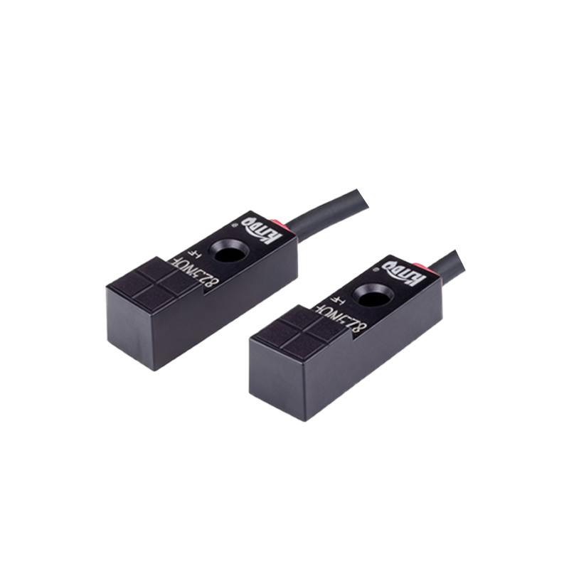
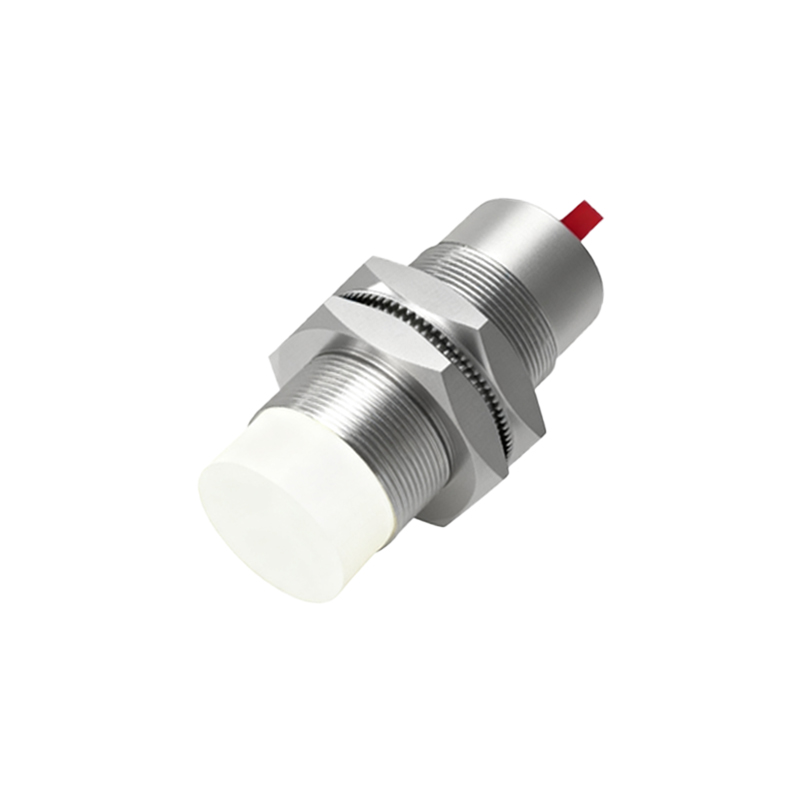
Proximity switch sensors operate based on different principles, including inductive, capacitive, ultrasonic, and optical methods. Each type has a distinct symbol to denote its specific sensing mechanism. The most common symbol for a proximity switch in schematics is a diamond shape with two parallel lines extending from it, often accompanied by additional markings to indicate the sensor type. For inductive proximity sensors, which detect metallic objects, the symbol typically includes a coil-like element inside or near the diamond. Capacitive sensors, capable of detecting both metallic and non-metallic materials, may feature two parallel plates within the symbol. Optical proximity sensors, using light beams, are represented with a diode-like arrow to signify emission and reception.
In electrical diagrams, these symbols are integrated into circuits to show how sensors interact with other components like PLCs (Programmable Logic Controllers), relays, and actuators. The symbol usually includes terminals for power supply and output signals. For instance, a three-wire proximity switch symbol will have connections for positive voltage, ground, and output signal. The output can be normally open (NO) or normally closed (NC), indicated by a break or continuity in the symbol lines. Engineers must interpret these symbols correctly to ensure proper wiring and functionality. Misreading a symbol can lead to system failures or safety hazards.
Standardization bodies like IEC (International Electrotechnical Commission) and IEEE (Institute of Electrical and Electronics Engineers) provide guidelines for these symbols to maintain consistency across industries. However, variations may exist based on regional practices or company-specific standards. It is essential for professionals to refer to relevant documentation, such as IEC 60617 or ANSI/IEEE Std 91, when designing or analyzing schematics. Additionally, modern CAD (Computer-Aided Design) software often includes libraries of these symbols, streamlining the drafting process.
Understanding proximity switch sensor symbols enhances troubleshooting and maintenance efforts. Technicians can quickly identify sensor locations and types in complex diagrams, reducing downtime in industrial settings. As automation advances, with trends toward IoT (Internet of Things) and smart factories, these symbols evolve to include digital interfaces and network connections. Future schematics may incorporate new symbolic elements to represent wireless or smart sensors, but the core principles of clarity and standardization will remain vital.
In summary, the symbol for a proximity switch sensor is more than just a drawing; it is a language that conveys critical technical information. Mastery of this symbolic language enables engineers and technicians to design, implement, and maintain efficient automated systems. By adhering to international standards and staying updated on emerging trends, professionals can ensure accurate communication and optimal performance in electrical projects.